 |
|||
|
Page Title:
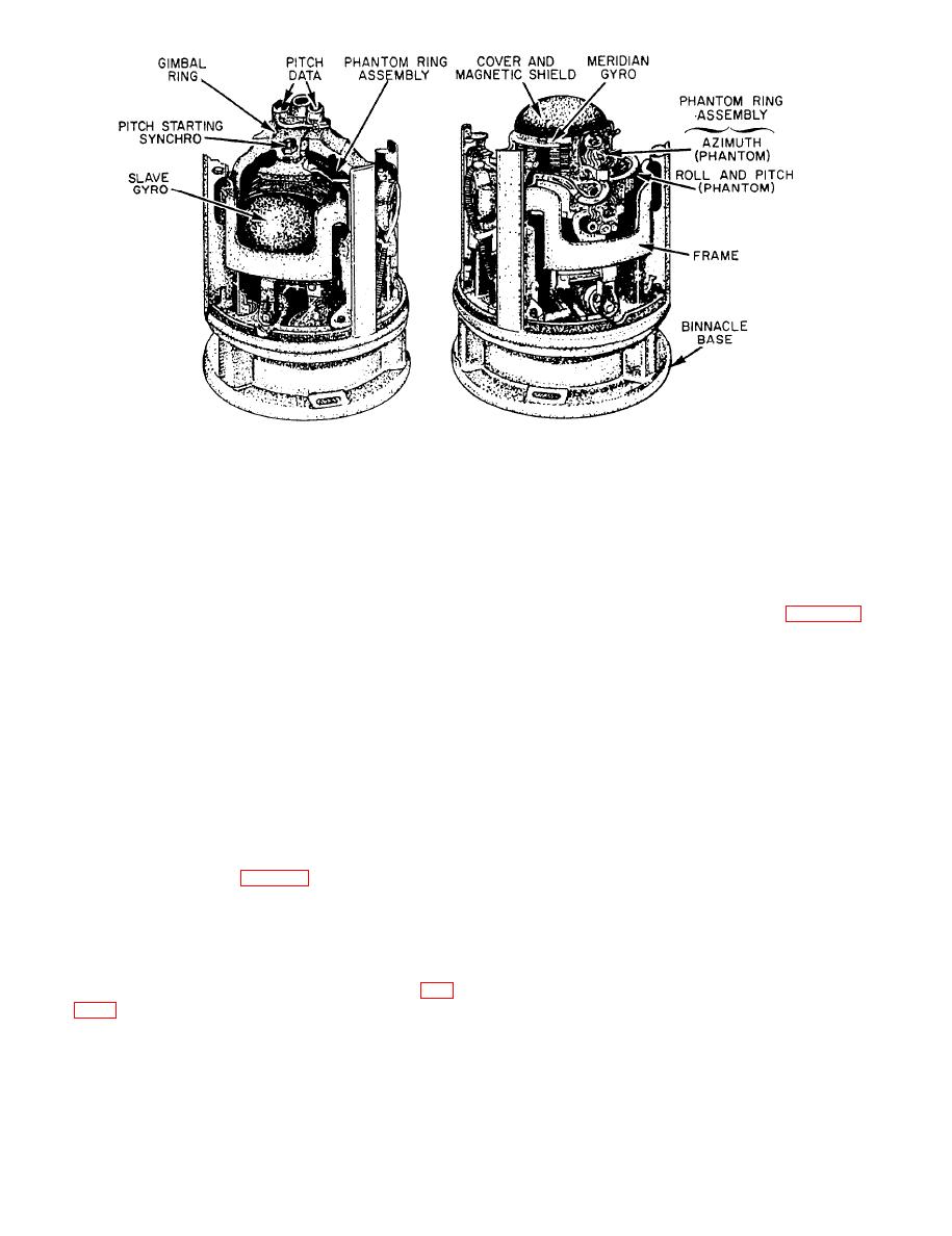
Figure 4-21.--Two views of master compass element and supporting element. |
|
||
| ||||||||||
|
|
 personnel, damage to the controls, or accidental change
phantom assembly, the meridian gyro on top, and the
of setting.
slave gyro, upside down, on the underside. The gyro
motors are 2-pole, 115-volt, 3-phase, 400-Hz squirrel
COMPUTER INDICATOR PANEL.-- Located
cage induction motors. The meridian gyro rotates
below the control panel, and inside the cabinet, are seven
approximately 23,600 rpm clockwise viewed from the
computer assemblies for computing data for the
south, and the slave gyro rotates at the same speed
systems. The computer indicator panel (fig. 4-23)
counterclockwise viewed from the east.
consists of seven windows. A dial is visible behind each
window to indicate the data being computed by its
The azimuth phantom is made to follow the azimuth
associated computer assembly. These assemblies are
motion of the meridian gyro and 1- and 36-speed
discussed later under the control system in which they
heading data are transmitted by the azimuth servo and
are used.
synchro assemblies mounted on the phantom assembly.
The roll and pitch phantom is stabilized in roll and pitch,
COMPUTER CONTROL ASSEMBLY.-- To
and 2- and 36-speed roll and pitch data are transmitted
minimize the number of amplifiers used in the system,
by the roll and pitch servo and synchro assemblies
two types of standard plug-in computer amplifiers are
mounted on the frame and binnacle.
used in 13 applications. As the characteristics and the
circuits in which the amplifiers are used vary, other
Control Cabinet
components peculiar to a single circuit must also be
used. For this reason, a T-shaped panel, known as the
The control cabinet (fig. 4-20) contains the control
computer control assembly, is located inside the control
panel, the computer indicator panel, a dc power supply,
cabinet. This panel provides a junction box into which
analog computers, amplifiers, and other assemblies
the amplifiers may be plugged. This panel also serves
required for operating and indicating the condition of
as a chassis for the various components required to
the master compass.
match the standard amplifiers to the particular circuits
concerned. The computer control assembly houses 11
type 1, and 2 type 2 general-purpose computer
amplifiers, and all the components required to operate
indicator fuses required for operating the system. Only
the various computer and torque circuits, other than
the controls required for normal operation of the system
those contained in the mechanical assemblies or in the
are accessible when the control cabinet is closed. These
master compass.
controls are on a recessed panel to avoid injury to
|
|
Privacy Statement - Press Release - Copyright Information. - Contact Us |