 |
|||
|
|
|||
| ||||||||||
|
|
 burrs to prevent chafing of the cable. Kickpipes,
form a laced cable with breakoffs, carefully estimate
including the stuffing tube, should have a minimum
the length of the longest conductor. Then add
height of 9 inches and a maximum of 18 inches. If the
approximately 2 1/2 times its length, and mark this
height exceeds 12 inches, a brace is necessary to
position with friction tape. The extra cable length will
ensure rigid support. If the installation of kickpipes is
allow for mistakes in attaching terminal lugs and
required in nonwatertight decks, a conduit bushing
possible rerouting of the conductors inside the
may be used in place of the stuffing tube.
equipment. You now know the length of the cable and
can cut it.
When three or more cables pass through a deck in
a single group, riser boxes must be used to provide
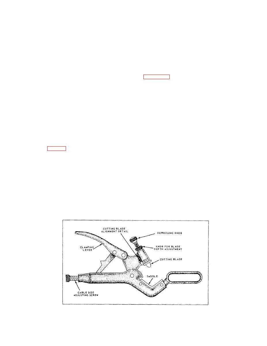
STRIPPING CABLE.-- The cable armor maybe
protection against mechanical damage. Stuffing tubes
removed by using a cable stripper of the type shown
are mounted in the top of riser boxes required for
in figure 2-52. Care must be taken not to cut or
topside weather-deck applications. For cable passage
puncture the cable sheath where the sheath will contact
through watertight decks inside a vessel, the riser box
the rubber grommet of the nylon stuffing tube.
may cover the stuffing tubes if it is fitted with an
Next, remove the impervious sheath, starting a
access plate of expanded metal or perforated sheet
distance of at least 1 1/4 inch (or as necessary to fit the
metal. Stuffing tubes are not required with riser boxes
requirements of the nylon stuffing tube) from where
for cable passage through nonwatertight decks.
the armor terminates. Use the cable stripper for this
job. Do not take a deep cut because the conductor
Connecting Cable
insulation can be easily damaged. Flexing the cable
will help separate the sheath after the cut has been
When connecting a newly installed cable to a
made. Clean the paint from the surface of the
junction box or unit of IC equipment, the length of the
remaining impervious sheath exposed by the removal
cable must be carefully estimated to ensure a neat
of the armor. This paint is conducting. It is applied
installation (fig. 2-51). To do this, form the cable run
during manufacture of the cable and passes through
from the last cable support to the equipment by hand.
the armor onto the sheath. Once the sheath has been
Allow sufficient slack and radius of bend to permit
removed, the cable filler can be trimmed with a pair
repairs without renewal of the cable. Carefully
of diagonal cutters.
estimate where the armor on the cable will have to be
cut to fit the stuffing tube (or connector), and mark the
CABLE ENDS.-- When a cable is terminated in
location with a piece of friction tape. In addition to
an enclosed equipment through a metal stuffing tube,
serving as a marker, the tape will prevent unraveling
the cable jacket must be tapered and any cavities filled
and hold the armor in place during cutting operations.
with plastic sealer to prevent possible water transit in
Determine the length of the cable inside the
the event of flooding. The tapered section is then
equipment, using the friction tape as a starting point.
wrapped with synthetic resin tape, and the end of the
Whether the conductors go directly to a connection or
tape served with treated glass cord.
2-47
|
|
Privacy Statement - Press Release - Copyright Information. - Contact Us |
