 |
|||
|
Page Title:
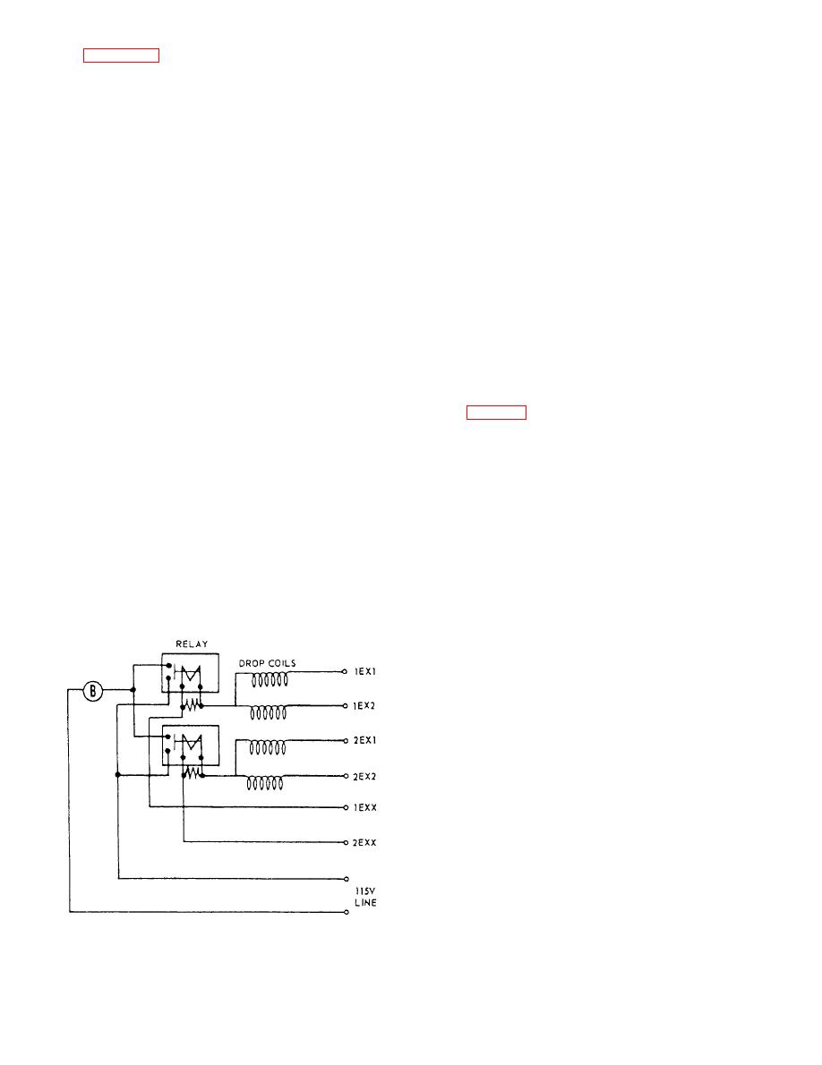
Figure 5-21.--Two-circuit, four-drop annunciator. |
|
||
| ||||||||||
|
|
 CIRCUIT EM - SOUND-POWERED
TELEPHONE SIGNAL
four-drop annunciator. Stations that have several
CIRCUIT
sound-powered telephones, each on a different circuit,
are provided with drop-type annunciators to identify the
circuit of the station that originates the call. Each drop
Circuit EM provides a means of signaling between
is embossed with the circuit letter and is held
sound-powered telephone stations, where more than six
mechanically in the nonindicating (normal) position.
stations are to be called by the calling station. Circuit
There is also an audible signaling device provided with
EM is divided into the same functional circuits as circuit
the annunciator.
E except that 1EM through 5EM is used. Circuit EM
uses type IC/D call signal stations, which require no
One side of each drop and one side of an
external power, and provides the operator with selective
audible-signal relay are connected together. When the
calling of up to 16 individual stations. The associated
circuit is energized by operating a switch at the calling
sound-powered telephone circuit is independent of the
station, the current flows through the drop and the relay.
signal circuit and provides the voice communication
The audible-signal relay closes its contacts to the
facilities between stations. Each sound-powered
audible signal and an electromagnet causes the proper
telephone circuit can accommodate only one
drop to fall to the indicating position. The audible signal
conversation over its facilities. The IC/D call signal
sounds only while the switch is operated. The drop is
station (fig. 5-22, views A and B), normally called a
returned to its normal position by a hand-operated reset
growler or a howler, uses a magneto generator to
button.
transmit a noninterrupted or interrupted signal to a
selected station.
The annunciator maybe equipped with one or more
audible-signal relays as required by the number of
associated circuits, but only one common audible signal
IC/D Noninterrupted Call Signal
device is used.
Station
The IC/D noninterrupted call signal station is made
of cast aluminum, with all of the equipment mounted on
the cover except for the terminal board and a
sound-powered jack outlet. Equipment mounted on the
cover include a 16-position rotary selector switch, an
index plate, a hand-operated magneto generator, a
howler unit, and an attenuator. The associated
sound-powered telephone circuit may be either the
string or the switchboard type.
To operate the station, you simply turn the rotary
selector switch to the station to be called and crank the
magneto generator handle. The howler (a modified
sound-powered telephone receiver unit) at the selected
station will produce a high distinctive howl. The howl
will continue for as long as the calling station generator
is cranked. The attenuator is used to control the volume
of the individual howler at its respective station. Each
EM circuit station is equipped with an IC/D call signal
|
|
Privacy Statement - Press Release - Copyright Information. - Contact Us |
