 |
|||
|
Page Title:
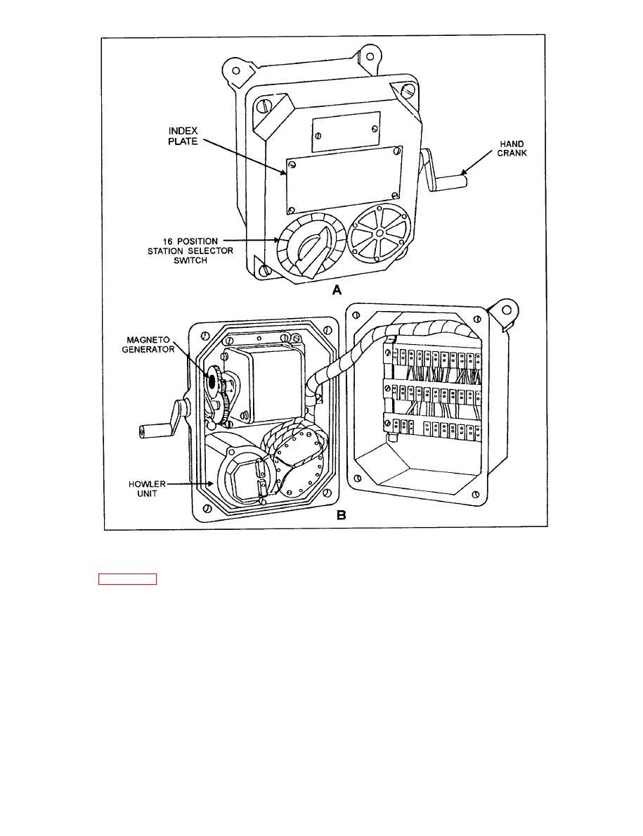
Figure 5-22.--IC/D call signal station. A. External view. B. Internal view. |
|
||
| ||||||||||
|
|
 IC/D Interrupted Call Signal Station
station. Figure 5-23 is an elementary wiring diagram of
the 2EM (ship control) circuit.
This station is identical to the noninterrupted
The call signal stations located in noisy spaces may
station, except the hand-operated magneto generator has
include a visual indicator lamp to alert personnel of an
been modified to generate a pulsating voltage. When the
incoming call. A relay box nippled to an indicator lamp
generator handle is cranked, the pulsating voltage
produced will provide an interrupted howl at the
is installed adjacent to each call signal station. The relay
selected station.
coil is connected to the howler circuit of the station. The
relay contacts are connected to the nearest emergency
This call signal station is used along with the
lighting circuit. When the station howler is activated, the
noninterrupted call signal station in a space where two
relay coil is energized and the relay contacts operate to
different circuits are required; thus providing different
audible signals to alert personnel as to which station is
complete the circuit from the lighting system to energize
being called.
the indicator lamp.
|
|
Privacy Statement - Press Release - Copyright Information. - Contact Us |
