 |
|||
|
Page Title:
Figure 5-16.--Functional diagram of AM-2210/WTC. |
|
||
| ||||||||||
|
|
 The switching circuit is activated when the
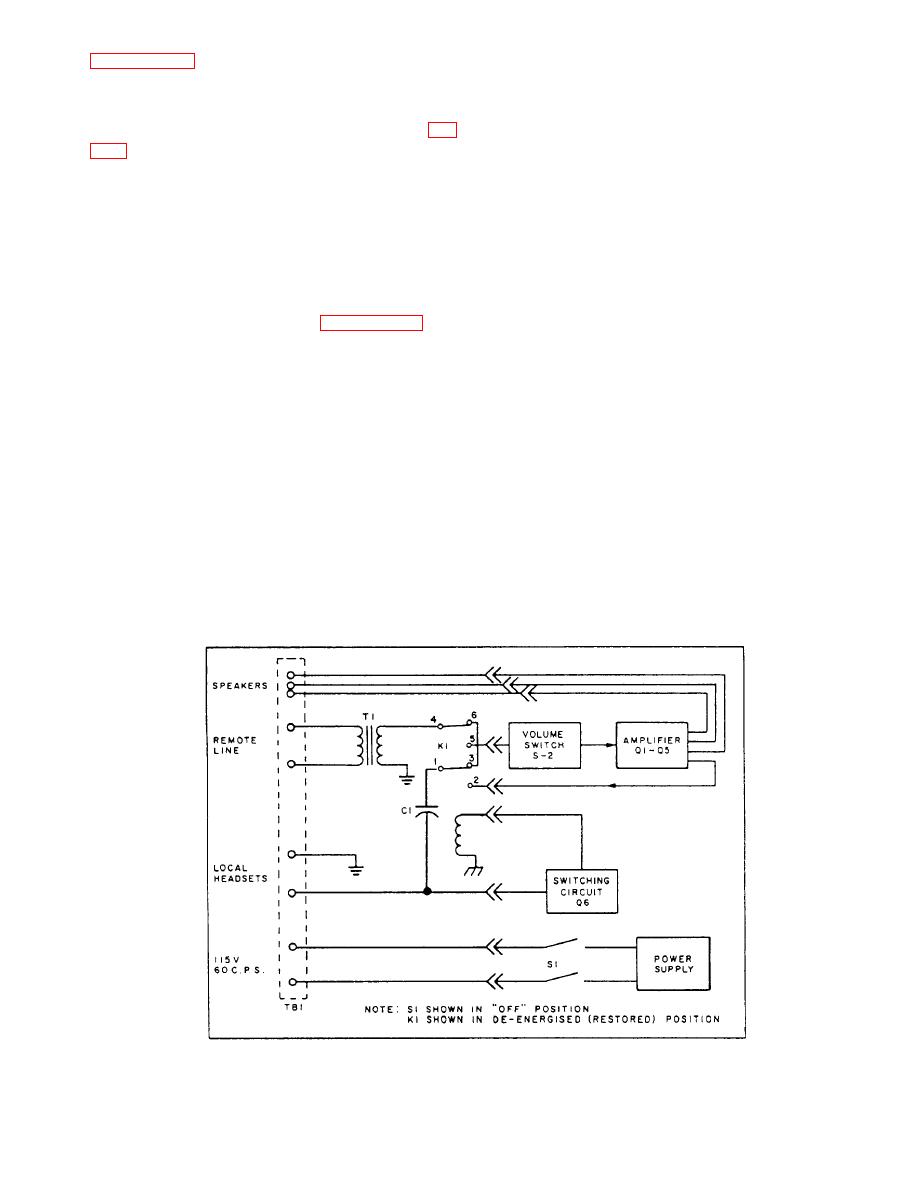
Figure 5-16 is a functional diagram of the
amplifier is energized. With power available and neither
AM-2210/WTC. One relay (K1) is used in the switching
local nor remote talk switches closed, the relay (K1) is
circuit.
operated. When operated, the depression of a remote
talk switch will have no effect upon K1; that is, it will
remain operated. However, when one of the six local
(Q1 through Q3) and a power amplifier (Q4 and Q5),
talk switches is depressed, the circuit to K1 is changed
with negative feedback employed throughout. The
and K1 restores.
output transformer (T3, not shown) has two
Resistor R31 provides a bias to the base of Q6,
secondaries: the first is used with the loudspeakers and
which normally holds Q6 in a saturated state,
the latter, a tapped winding, is used for as many as six
maintaining K1 in an operated condition. When the local
sound-powered telephone outlets. The amplifier
talk switch is closed, the base of Q6 is connected to
provides a 10-watt output.
ground through the 4.8 ohms of the mouthpiece.
Presently the voltage across Q6 from base to ground
functional representation of the K1 switching circuit,
becomes less than the emitter bias voltage provided by
voltage divider network R32 and R33; therefore, the
showing K1 in an energized and operated condition. The
transistor becomes reverse biased and Q6 becomes
receiver element of the local headset-chestset is in series
nonconductive, de-energizing and restoring K1.
with a dc blocking capacitor, thereby presenting a high
resistance when the talk switch is open. Closing the talk
The incoming and outgoing voice signals are
switch connects the headset across the line, giving the
coupled through capacitor C1 of the amplifier. CR1 is
headset a dc resistance of approximately 4.8 ohms. It is
in the circuit to protect Q6 from surges while it is in the
the function of the switching circuit to sense this change
cutoff state.
from high impedance to low resistance that takes place
with the depression of one of the six headset-chestset
The restoration of K1 will result in normal
communications at sound-powered level between all
talk switches.
5-18
|
|
Privacy Statement - Press Release - Copyright Information. - Contact Us |
