 |
|||
|
Page Title:
Figure 5-17.--Switchlng circuit of AM-2210/WTC. |
|
||
| ||||||||||
|
|
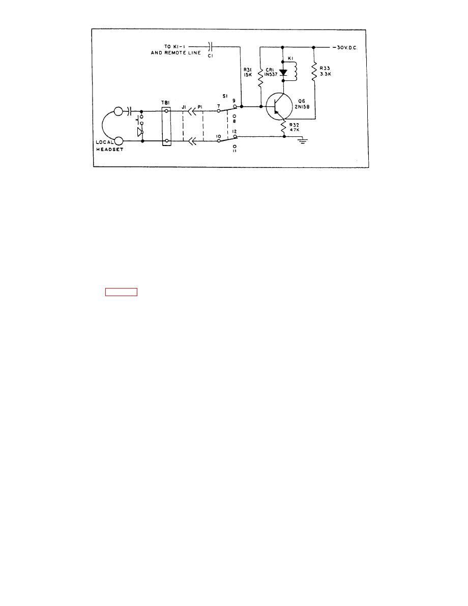 out and communications between any of the local and
stations. The amplifier is effectively bypassed. The
remote stations takes place at the normal sound-
advantage of this circuitry is that any casualty, such as
powered level.
loss of power, will allow normal sound-powered
communications to continue.
Amplifier Maintenance
POWER SUPPLY.-- The power supply is
basically a full-wave rectifier receiving its power
Although by no means trouble free, the
through switch S1 (fig. 5-16) and the fuses on the face
AM-2210/WTC is a highly reliable piece of equipment.
of the amplifier. A neon glow lamp and a volume control
When trouble does occur, it is often caused by improper
potentiometer are also located on the face of the
operating procedures or by a failure in external circuitry.
amplifier. The amplifier operates on 115-volt, 60-Hz,
Often personnel who operate the amplifier are not aware
single-phase power, which is normally supplied by the
of its operational capabilities, and a brief indoctrination
ship's local lighting panels.
will clear up an apparent trouble.
One procedure that has caused some failures in the
are amplified and delivered to local headset-chestsets
amplifier is the practice of taping closed the talk button
and loudspeakers. The volume control knob located on
of one of the local headset-chestsets. This violation of
the face of the amplifier is used to adjust the desired
circuit integrity will result in K1 being continually
headset-chestset receiver output volume. The output
restored, resulting in no amplification of incoming
volume for the associated loudspeakers is adjusted
signals.
locally at the loudspeakers. The circuit associated with
You should accomplish preventive maintenance
the telephone amplifier operates under the three
using the applicable maintenance requirement cards
following conditions:
( M R C s ) . You should accomplish corrective
maintenance according to the applicable technical
1. When the amplifier is de-energized, direct
manual.
two-way communication between local and remote
stations takes place at the normal sound-powered level.
AMPLIFIER CONTROL SWITCHES
2. When the amplifier is energized, incoming
signals from the remote line are amplified and
At stations where it is desired to maintain two-way
transmitted to the local stations and associated
communication for all circuits serving the station, an
loudspeakers.
amplifier control switch is installed. This switch
provides the operator with a means of selecting anyone
3. When the amplifier is energized and the talk
of several circuits to be amplified while retaining
switch of any local station is closed, the amplifier is cut
|
|
Privacy Statement - Press Release - Copyright Information. - Contact Us |
