 |
|||
|
Page Title:
Figure 4-15.-Degenerated CE configuration. |
|
||
| ||||||||||
|
|
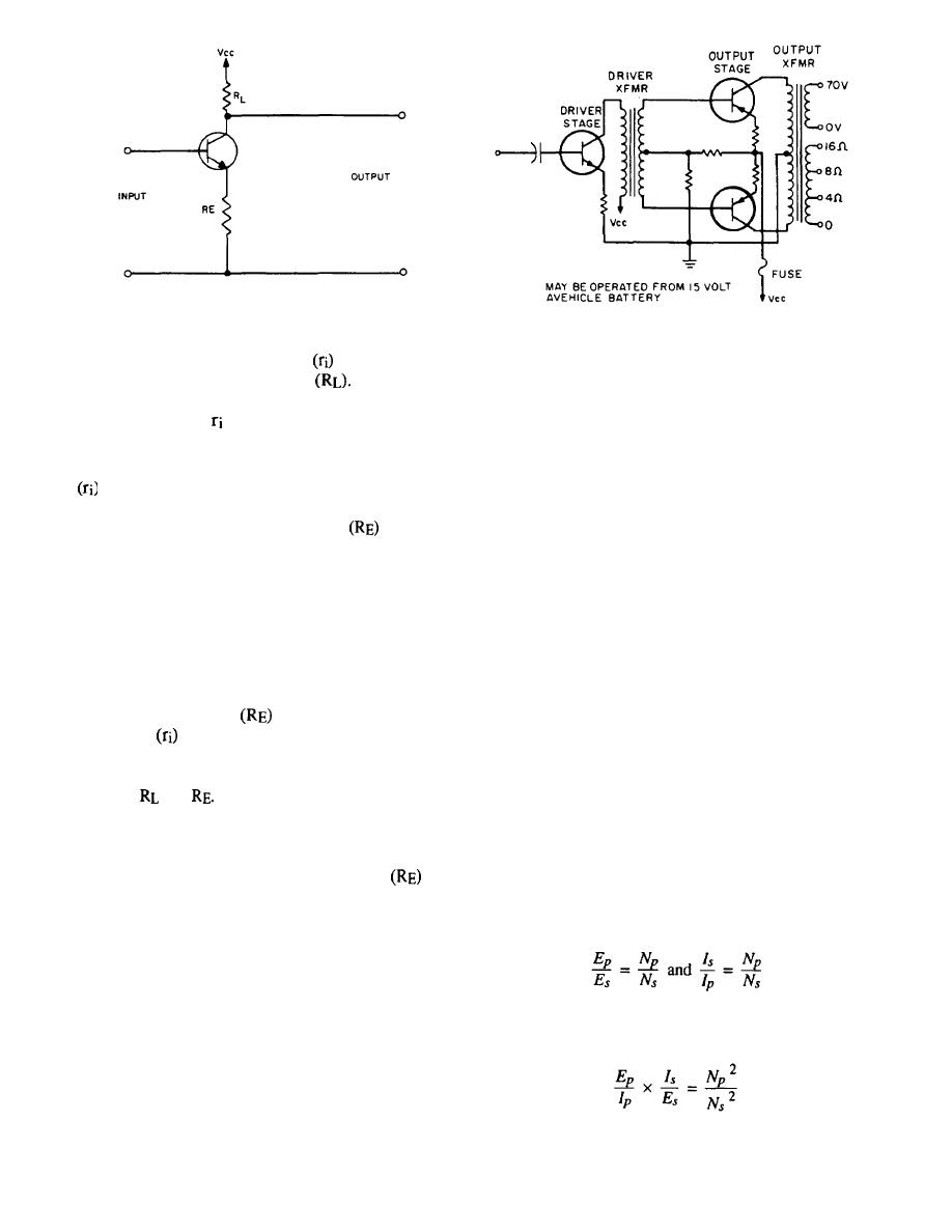 Figure 4-15.-Degenerated CE configuration.
Figure 4-16.-Basic transistor output stages using two
transformers.
ohms is used. The input resistance
may be increased
by reducing the load resistance
For instance,
mismatch of the transistor and the speaker. The output
decreasing the load resistance to approximately 10,000
transformer in a basic audio output stage (fig. 4-16)
ohms will increase to approximately 1,500 ohms, as
seen in the curve of figure 4-13.
matches the low impedance of the speaker coil to the
high impedance of the output transistor. The primary of
Another method of increasing the input resistance
the transformer has more turns for high impedance; the
of a CE configuration is shown in figure 4-15. This
secondary has fewer turns to provide the low impedance
t y p e of circuit is the DEGENERATED CE
required by the speaker coil.
configuration. If an unbypassed resistor
is inserted
in the emitter lead, the signal voltage developed across
For a certain transistor, you can find the resistive
this resistor opposes the input signal voltage.
value (impedance) that provides maximum gain with
As in the case of the CC configuration, this
minimum distortion by consulting a transistor manual.
negative-feedback voltage or degenerative voltage
Typical values range from approximately 2,000 to 5,000
causes an increase in the input resistance. With a
ohms for one transistor, and they are doubled for
bypassed resistor in the emitter lead, the input resistance
push-pull outputs. Power to the secondary of a
of the CE configuration would be 2,000 ohms if a load
transformer is nearly equal to the power supplied by the
resistor of 500 ohms were used (fig. 4-13). With an
primary due to the near unity coupling of the iron core
of 500 ohms, the input
unbypassed resistor
in the transformer. The amount of power that an output
will appear as approximately 20,000
resistance
transformer can handle is determined by the current and
ohms. The input resistance may be made to appear as
voltage ratings of its windings and by allowable losses.
any desired value (within practical limits) by the proper
choice of
and
Like the CE circuit with the series
resistor, the total input resistance of the degenerated CE
IMPEDANCE RATIO
circuit will remain relatively constant with a varying
load. However, the advantage of the degenerated CE
Recall that the output voltage of a transformer varies
configuration is that the unbypassed resistor
also
directly with the turns ratio and that the output current
acts as an emitter stabilizer and aids in stabilizing the
varies inversely with the turns ratio. The proportions in
transistor bias.
equation form are
AUDIO OUTPUT STAGE
The voice coil of a dynamic speaker requires a
Multiply these proportions to get
low-impedance source, but the impedance of an output
transistor is high. If the speaker is connected directly to
the collector of the transistor, there is almost no audio
because the transistor has no gain, due to the loss in
4-16
|
|
Privacy Statement - Press Release - Copyright Information. - Contact Us |
