 |
|||
|
Page Title:
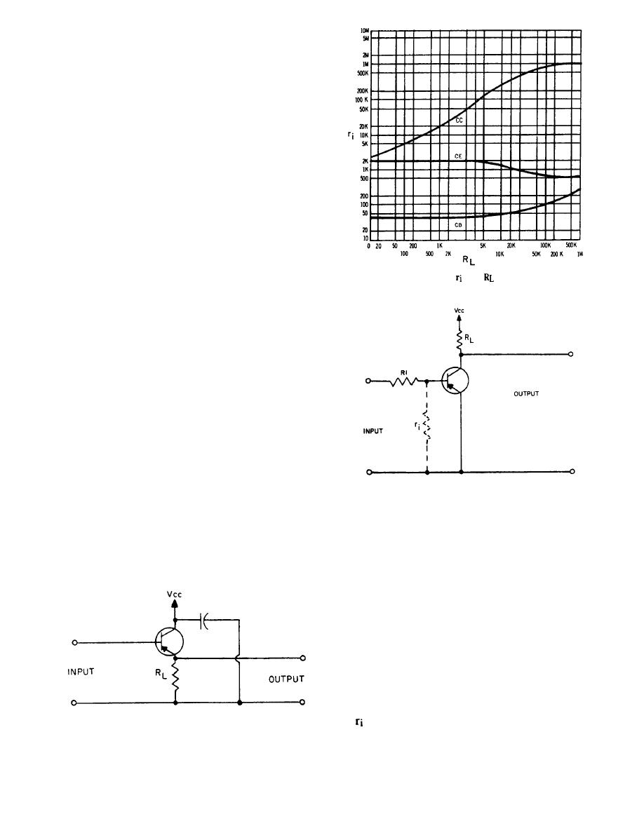
Figure 4-13.-Variations of with for each configuration. |
|
||
| ||||||||||
|
|
 Vacuum-tube amplifiers are easier to service on
the bench.
IMPEDANCE MATCHING IN AMPLIFIERS
Amplifiers must sufficiently amplify an input signal
to the point where it may be applied to a power amplifier.
Due to their high input impedance, electron tubes cause
few impedance matching problems. While the input
impedance for transistors may be high in some
configurations, transistor circuits are nevertheless more
troublesome in this respect. A more detailed discussion
will now be given on how the effects of the input
impedance determine the choice of transistor
configurations.
The most desirable method of matching source
impedance to input impedance is by transformer
coupling; however, this is not always practical. When
Figure 4-13.-Variations of
with
for each configuration.
the preamplifier must be fed from a low-resistance
source (20 to 1,500 ohms), without the benefit of
transformer coupling, either the common base (CB) or
the common emitter (CE) configuration may be used.
The CB configuration has an input impedance that is
normally between 30 and 150 ohms; the CE
configuration has an input impedance that is normally
between 500 and 1,500 ohms.
If the signal source has a high internal impedance,
a high input impedance can then be obtained by using
one of the three following circuit arrangements.
The easiest configuration to use would be the
common collector (CC). The input resistance of the CC
configuration is high because of the large negative
voltage feedback in the base-emitter (BE) circuit. As the
input voltage rises, the opposing voltage developed
Figure 4-14.-Simplified schematic of a CE preamplifier with
series resister.
across the load resistance (fig. 4-12) substantially
reduces the net voltage across the BE junction. By this
action, the current drawn from the signal source remains
high impedance. If a load impedance of 500 ohms is
low. From Ohm's law, you should know that a low
used, the input resistance of a typical CC configuration
current drawn by a relatively high voltage represents a
will be over 30,000 ohms. The disadvantage of the CC
configuration, however, is that small variations in the
current drawn by the following stage cause large
changes in the input impedance value.
The variation of input impedance, as a function of
load impedance, for the CE, CB, and CC configurations
is shown in figure 4-13.
The CE configuration maybe used to match a high
source resistance by the addition of a series resistor in
the base lead. The BE junction resistance (represented
by in fig. 4-14) for a typical CE configuration is
Figure 4-12.-Simplified schematic of a CC preamplifier.
approximate y 1,000 ohms if a load resistance of 30,000
4-15
|
|
Privacy Statement - Press Release - Copyright Information. - Contact Us |
