 |
|||
|
|
|||
| ||||||||||
|
|
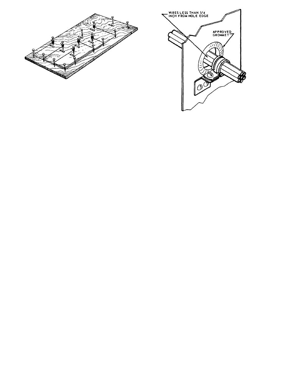 Figure 4-9.Harness form.
positions of the terminals on the board. Drive nails at
each terminal location and at points where the wires and
harness bend. Write the terminal designations near the
Figure 4-10.-Cable clamp and grommet.
appropriate nails, using the wiring diagram from the
equipment manual to double-check that terminal
markings are correct. When this is done, you can return
Wires passing through partitions or supports inside
the unit to service until it is convenient to install the new
a chassis must be supported at each hole by a cable
harness.
clamp or other permanent support. If the clearance
between the edge of the hole and the cable exterior is
The wires are run between the terminal points,
less than one-fourth of an inch, install a suitable
following the route outlined by the nails. Do not stretch
grommet in the hole (fig, 4-10).
the wires tight. The bitter ends of each wire are wrapped
around the nails located at its terminal positions. When
all terminals have been connected, the harness is formed
PREVENTIVE MAINTENANCE
and can be laced. If terminal connectors are to be used,
they are soldered in place after lacing is complete, and
The best maintenance is preventive, as potential
spaghetti put in place.
failures are detected and not given a chance to develop.
Preventive maintenance is defined as the measures
When the new harness is ready, you can install it in
taken periodically, or when needed, to achieve
a relatively short time. If it is to replace a harness in
maximum efficiency in performance, to ensure
equipment that is operating, the installation can be
continuity of service, and to lengthen the useful life of
postponed until the ship is in port or the unit is not
the equipment or system. This form of maintenance
needed.
consists principally of cleaning, lubrication, and
When installing or replacing wire or cable runs in
periodic inspections aimed at discovering conditions
equipment cabinets, make sure the slack between cable
that, if not corrected, may lead to malfunctions requiring
clamps is not excessive. Normally, wire should not sag
major repair.
by more than one-half of an inch when normal hand
pressure is applied. Allow enough slack at each end to
EQUIPMENT INSPECTIONS
prevent strain on the wire and to permit removal and
connection of plugs, replacement of terminal lugs, and
Equipment inspections fall into two main
free movement of shock and vibration-mounted
categories. First, there is the regular visual inspection of
equipment.
the mechanical aspects of the equipment. This
Bends in individual wires should not exceed a radius
inspection is conducted to find dirt, corrosion, loose
of 10 times the diameter of the wire or group of wires
connections, mechanical defects, and other sources of
except where the wire is suitably supported at each end
trouble. Second, there are functional inspections that are
of the bend; the minimum bend radius is 3 times the
accomplished by periodic testing and less frequent
diameter of the wire.
bench testing. To realize the most effective results from
4-11
|
|
Privacy Statement - Press Release - Copyright Information. - Contact Us |
