 |
|||
|
|
|||
| ||||||||||
|
|
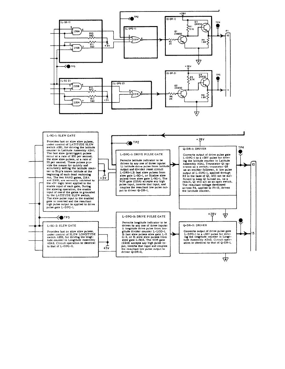
 Figure 4-1.-Blocked schematic.
Figure 4-2.-Blocked text.
signals being processed by the coded shape of an
entity i s easily and simply identified by a
arrowhead superimposed on the lines.
circuit-identifier code, such as Q-DR-1 or L-DPG-2. For
example, in Q-DR-1 (a driver stage), Q is the active
BLOCKED TEXT
element (a transistor); DR is the abbreviation for driver;
and 1 indicates the first occurrence of that type of
The blocked text (fig. 4-2) is presented on a page
functional entity in the assembly. Functional entities are
facing the blocked schematic. The arrangement of the
blocked text matches that of the blocked schematic.
connected by signal flow lines that show the kinds of
4-3
|
|
Privacy Statement - Press Release - Copyright Information. - Contact Us |