 |
|||
|
Page Title:
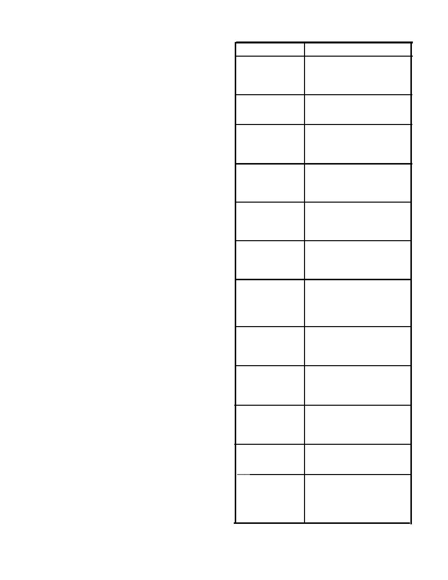
Table 3-2.-Electrica1 Power and Lighting Cable Markings |
|
||
| ||||||||||
|
|
 Table 3-2.-Electrica1 Power and Lighting Cable Markings
(4-168-1)-4P-A(1) (fig. 3-8) identifies a 450-volt power
cable supplied from a power distribution panel on the
fourth deck at frame 168 starboard. The letter A indicates
Cable Marking
Remarks
that this is the first cable from the panel, and the (1)
6SG-4P-6S
450-volt generator power cable
indicates that it is the first section of a power main with
for ship service switchboard #6
more than one section.
supplied from ship service
The power cables between generators and
generator #6.
switchboards are labeled according to the generator
designation. When only one generator supplies a
6S4P-7S
450-volt bus-tie power cable
between ship service switchboard
switchboard, the generator will have the same number
#6 and #7.
as the switchboard plus the letter G. Thus, 1SG denotes
one ship's service generator that supplies the number 1
450-volt switchboard
3SA-4P-3SB
ship's service switchboard. When more than one ship's
inter-connecting power cable
service generator supplies a switchboard, the first
between sections A and B of the
switchboard.
generator determined according to the general rule for
numbering machinery will have the letter A immediately
6S-4P-31
450-volt BUS FEEDER power
following the designation; the second generator that
cable from #6 switchboard
supplies the same switchboard will have the letter B.
supplying load center
This procedure is continued for all generators that
switchboard #1 in zone 3.
supply the switchboards. Thus, 1SG and 1SGB denote
450-volt power FEEDER cable
31-4P-(3-125-2)
two ship's service generators that supply ship's service
from load center switchboard #1
switchboard 1S.
in zone 3 supplying power
Representative cable markings for power and
distribution panel 3-125-2.
lighting circuits are listed and explained in table 3-2.
450-volt MAIN power cable
(3-125-2)-4P-C
supplied from power distribution
PHASE AND POLARITY MARKINGS
panel 3-125-2, the third cable
from the panel.
Phase and polarity in ac and dc electrical systems
(3-125-2)-1P-C1
120-volt SUBMAIN power cable
are designated by a wiring color code as shown in table
supplied from power panel
3-2. Neutral polarity, where it exists, is identified by the
3-125-2, the first cable fed
white conductor.
through a transformer by the
MAIN listed above.
ISOMETRIC WIRING DIAGRAM
(3-125-2)-1P-CIB
120-volt BRANCH power cable
supplied from power panel
An isometric wiring diagram is supplied for each
3-125-2, the second cable fed by
shipboard electrical system. If the system is not too
the submain listed above.
large, the isometric wiring diagram will be covered by
(3-125-2)-1P-C1B2
120-volt SUBBRANCH power
one blueprint. For large systems, several prints may be
cable supplied from power panel
required to show the complete system. An isometric
3-125-2, the second cable fed by
wiring diagram shows the ship's decks arranged in tiers.
the branch listed above.
Bulkheads and compartments are shown, the centerline
1E-1EL-A
120-volt MAIN emergency,
is marked, and the frame numbers are shown (usually
lighting cable supplied from #1
every five frames). The outer edge of each deck is drawn
emergency switchboard-the first
to show the general outline of the shape of the ship. All
cable from the switchboard.
athwartship lines are shown at an angle of 30 degrees to
2-38-1)-1L-A1
120-voh SUBMAIN ship service
the centerline. Cables running from one deck to another
lighting cable supplied from
are drawn as lines at right angles to the centerline. A
lighting panel 2-38-1.
cable, regardless of the number of conductors, is
represented on an isometric diagram by a single line.
(2-38-1)-1L-A1C3
120-volt SUBBRANCH ship
service lighting cable supplied
The various electrical fixtures are identified by a symbol
from lighting panel 2-38-1the
number and their general location is shown. Thus, the
third cable supplied by BRANCH
isometric wiring diagram shows a rough picture of the
cable (2-38-1)-1L-A1C.
entire circuit layout.
3-14
|
|
Privacy Statement - Press Release - Copyright Information. - Contact Us |