 |
|||
|
|
|||
| ||||||||||
|
|
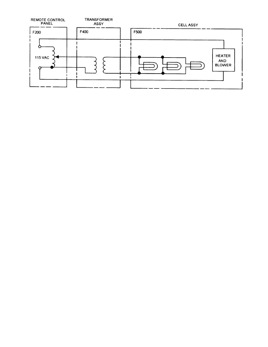
 Figure 3-21.--Cell power.
be set to internal gyro for internal stab-leek operation.
ship, the platform pitches or rolls an equal amount in the
opposite direction. Thus, the platform remains level to
While in this mode, the test switches and manual drive
the horizon or more precisely perpendicular to the local
potentiometer can be operated to enable insertion of
earth gravity vector.
signals independent of the local gyro. This mode enables
the operator to isolate and test various parts of the system
Operational Modes
while disabling other parts.
SHIP GYRO STABILIZATION MODE.- Ship
The system has four operational modes: internal
gyro stabilization is provided as an alternative to plat-
gyro, internal gyro stabilization lock ship gyro, and ship
gyro stabilization leek.
form-mounted internal gyro stabilization. The system
should be operated in the internal gyro mode unless
SGSI SYSTEM NORMAL OPERATING
component failure disables that portion of the circuitry
PROCEDURE.- Stabilization from the internal gyro
is the normal mode of system stabilization and is
since switching to the ship's gyro reduces system
preferred to ship gyro mode because of higher system
accuracy. The internal gyro/ship gyro switch-indicator
accuracy and addition of the gyro failure alarm. The
is on the component panel assembly. A ship gyro in-
system should always be operated in this mode as
dicator on the remote control panel serves to remind
opposed to ship gyro operation unless a system failure
system operators when the alternative stabilization
prevents it. Operating control is normally conducted
from the remote control panel from which the operator
source is in use.
can turn the system on and vary the intensity of the
SHIP GYRO STABILIZATION LOCK
source light. The system may also be turned on at the
MODE.- The ship gyro stabilization leek mode dis-
electronics enclosure assembly when the POWER
connects the ship's gyro signals at the input to the gyro
ON/OFF push button is depressed. Adjustment of the
signal card assembly and replaces them with ground
source light intensity, however, can only be adjusted
at the remote control panel. The normal mode is the
reference or manual drive potentiometer signals. This
interred gyro mode, where the gyro acts as the system
permits check-out and troubleshooting of ship gyro
sensor detecting any eviations from platform level. In
stabilization and stabilization error detecting circuitry.
this mode the platform will always remain level and
The internal gyro/ship gyro switch-indicator on the
cannot be offset.
component panel assembly should be placed in the ship
INTERNAL GYRO STABILIZATION LOCK
gyro position to enable the stabilized platform to track
MODE.- The internal gyro stab-leek mode disconnects
manual drive signals. The lamp control relay
internal gyro signals from the stabilization loop and
extinguishes GSI source lamps while operating in this
locks the platform in a neutral position for test, align-
ment, and troubleshooting purposes. The system must
stab-leek mode.
3-15
|
|
Privacy Statement - Press Release - Copyright Information. - Contact Us |