 |
|||
|
Page Title:
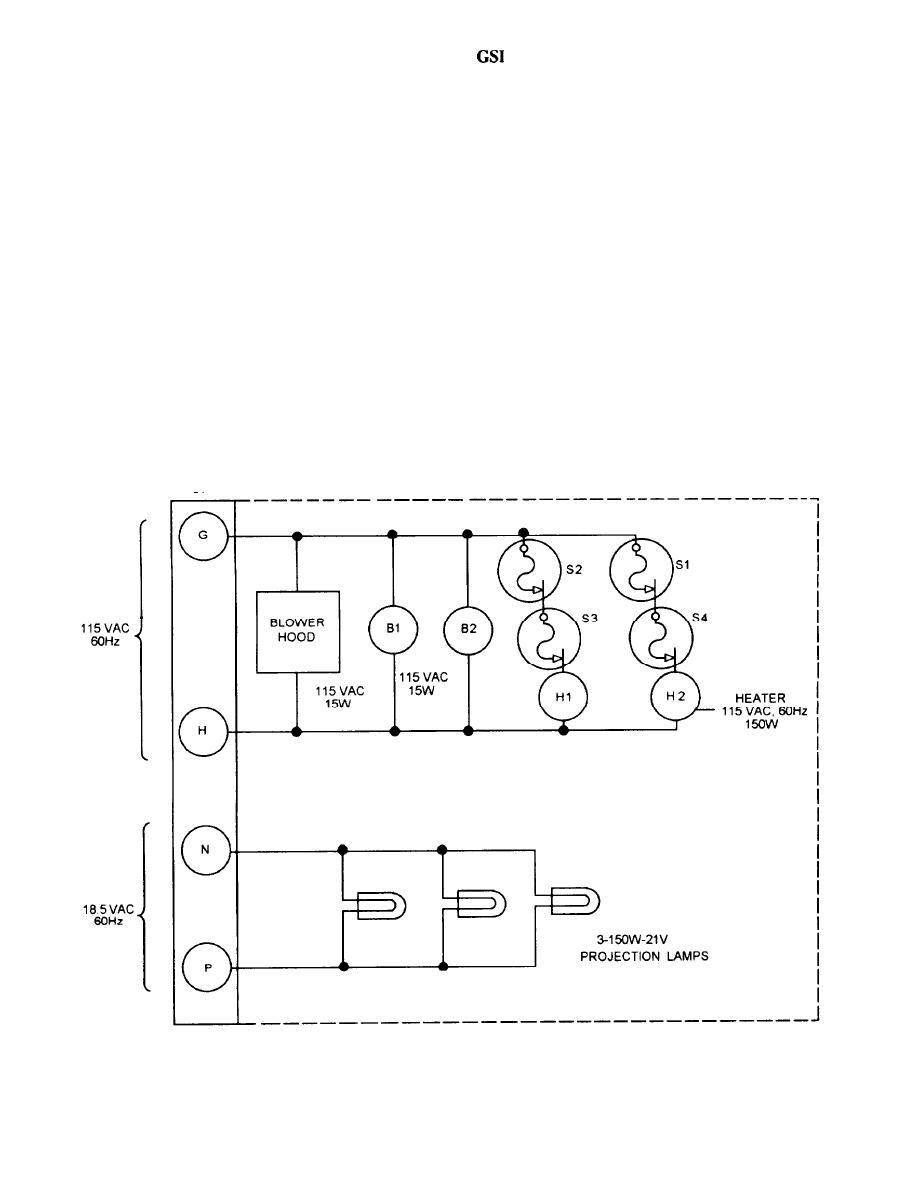
Figure 3-20.--GSI cell, simplified schematic. |
|
||
| ||||||||||
|
|
 TRANSFORMER
temperature control is achieved by blowers, heaters, and
thermal switches.
The GSI uses three 21-volt 150-watt projection
The temperature control circuits (see figs. 3-20 and
lamps for its light source. This is about 21 amps of
current and would cause considerable voltage drop if
3-21) are used to regulate operating temperatures in the
long cables were used, thus the transformer assembly is
GSI assembly. When power is applied at the remote
mounted close to the GSI light and uses a fixed length
control panel, voltage is applied to the heaters and
of cable (10 feet) from the transformer secondary to
blowers to the left and right of the lens assemblies.
the GSI cell connector. The system autotransformer
Blower motors B1 and B2 begin to operate as soon as
supplying the primary voltage to the transformer is
located in the remote control panel. A simplified
voltage is applied. Control thermoswitches S1 and S2
schematic is shown in figure 3-21.
are set at 100 +10F. To keep this temperature constant,
S1 and S2 open and close as the temperature rises and
STABILIZED PLATFORM SYSTEM
falls in the GSI assembly. As the thermoswitches open
The stabilized platform system is an electro-
and close, power is removed from or applied to heaters
hydraulic served platform used to stabilize the GSI
H1 and H2. If S1 and S2 fail to open, backup thermo-
against the ship's pitch and roll. This keeps the tricolored
switches S3 and S4 will open, preventing damage to the
GSI light at a fixed angle to the horizon. The
lenses. A simplified schematic of the cell wiring appears
stabilization is termed a one-to-one stabilization system.
This means that for each degree of pitch or roll of the
in figure 3-20.
Figure 3-20.--GSI cell, simplified schematic.
3-14
|
|
Privacy Statement - Press Release - Copyright Information. - Contact Us |
