 |
|||
|
Page Title:
Synchro Connections of a Synchro Amplifier |
|
||
| ||||||||||
|
|
 A synchro amplifier cycle of operation takes place
S2 to terminal block terminal B2
as follows:
S3 to terminal block terminal B3
1. A change occurs in the remotely transmitted
When the shaft of the synchro is to be driven clockwise
synchro data.
for an increasing reading, the connections to the
2. The signal received by the synchro control
terminal bus should be as follows:
transformers in the mechanical unit is, as an error volt-
R1 to terminal block terminal B
age, amplified and used to operate the servomotor. The
R2 to terminal block terminal BB
servomotor, through gearing, turns the synchro control
transformer rotors until the error voltages are zero (or,
S3 to terminal block terminal B1
in the low-speed unit, matched to the stickoff voltage),
S2 to terminal block terminal B2
thereby stopping the turning or follow-up action.
S1 to terminal block terminal B3
3. Simultaneous with step 2, the servomotor also
drives the rotors of the output synchros into alignment
For a synchro control transformer, these con- nections
with the new input signal.
will apply to the stator, but the rotor connections go to
the input of the servo amplifier.
Synchro Connections of a Synchro Amplifier
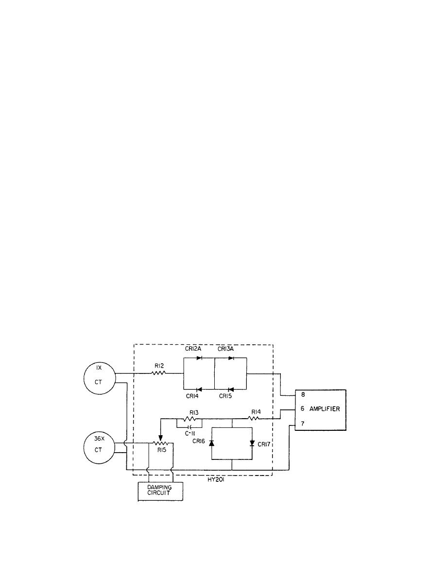
Cutover Circuit
The conventional connection is for counterclock-
wise rotation for increasing reading-an increasing read-
The purpose of the cutover circuit is to auto-
matically select the error voltage from either the high
ing is when the numbers associated with the action being
measured are increasing. The five wires of a synchro
(36 speed) or low (1 or 2 speed) synchro control
system are numbered in such a way that the shaft of a
transformer and feed it to the servo-amplifier input
normal synchro will turn counterclockwise. When an
terminals. The low-speed control transformer is
increasing reading is sent over the wires provided, the
connected when the error is large (more than 2 1/20),
and the high-speed control transformer is connected
synchro is connected as follows:
when the error is small (less than 2 1/20).
R1 to terminal block terminal B
The cutover circuit (fig. 2-12) consists of six diodes
R2 to terminal block terminal BB
(CR12A through CR17) and three resistors (R12, R13,
S1 to terminal block terminal B1
and R14). The circuit operates on the principle that
Figure 2-12.--Cutover circuit.
2-11
|
|
Privacy Statement - Press Release - Copyright Information. - Contact Us |
