 |
|||
|
Page Title:
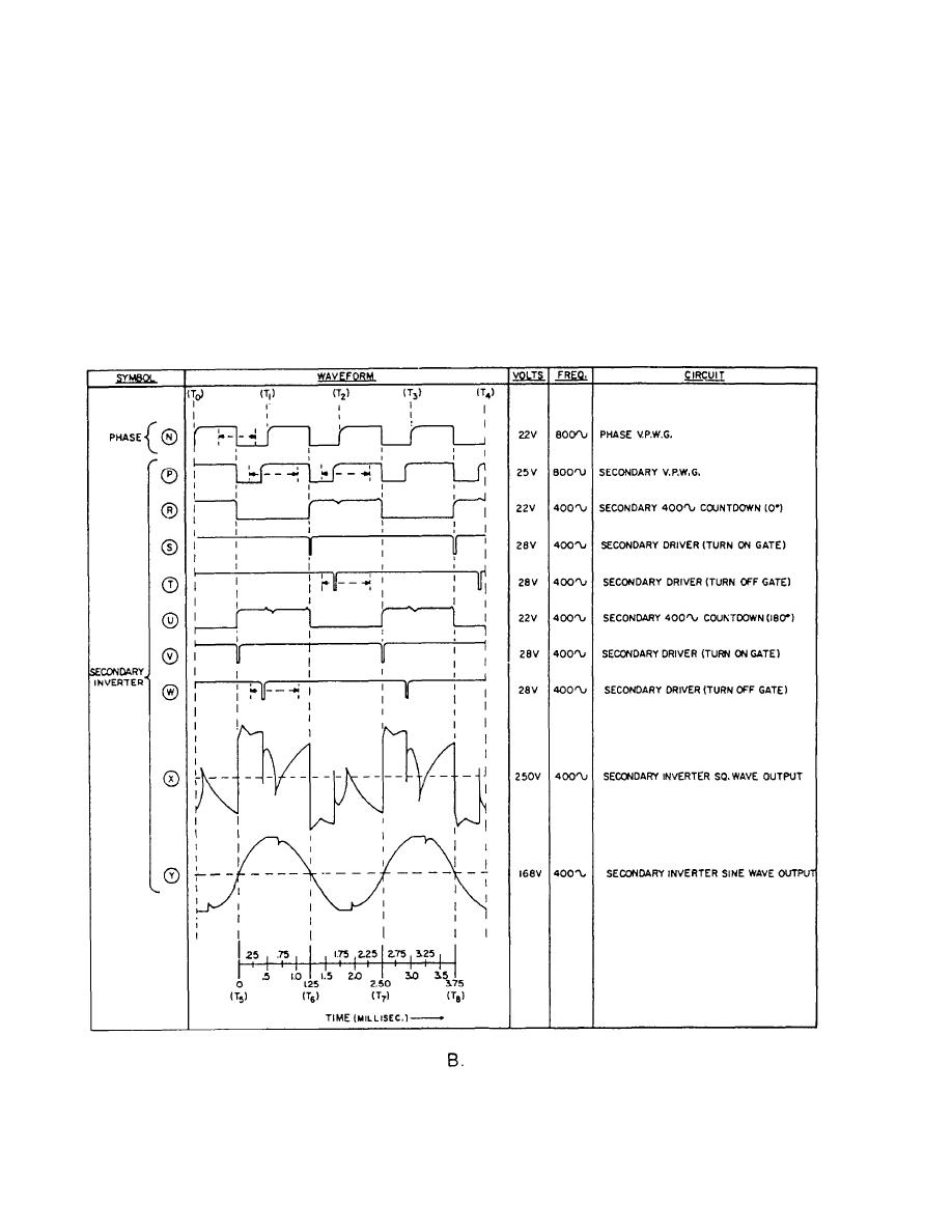
Figure 1-40.-WaveformsContinued. |
|
||
| ||||||||||
|
|
 voltage-sensing network composed of resistors and
composed of a transient and a steady-state condition.
capacitors is connected to the bus that supplies the de
The transient condition lasts for approximately
input to the inverter. Positive and negative step changes
2 seconds. This 2-second time delay is provided by the
in the dc supply voltage produce positive and negative
delayed B+ voltage interlock to allow the inverter
pulse outputs from the voltage-sensing network. The
circuits to reach a steady state as mentioned previously.
output pulses are fed to the pulse width modulator circuit
in the main and secondary VPWGs to compensate for
During the standby mode, the 800-Hz countdown
the voltage change.
circuit of the oscillator supplies an 800-Hz square-wave
voltage to the SYNC stage and the main VPWG (wave-
OPERATION CYCLE
form B, fig. 140, view A, and fig. 1-38). A+30-volt dc
signal is applied to the binary circuit in the SYNC stage
When the main power circuit breaker is ON and
via the drive switch (S1, fig. 1-37) that keeps the bistable
the drive switch is in the OFF position, the inverter is in
multivibrator in the SYNC stage in the "turnoff' state.
the standby mode of operation. The standby mode is
Figure 1-40.-WaveformsContinued.
1-35
|
|
Privacy Statement - Press Release - Copyright Information. - Contact Us |
