 |
|||
|
Page Title:
Figure 1-10.-AND symbol and circuit. |
|
||
| ||||||||||
|
|
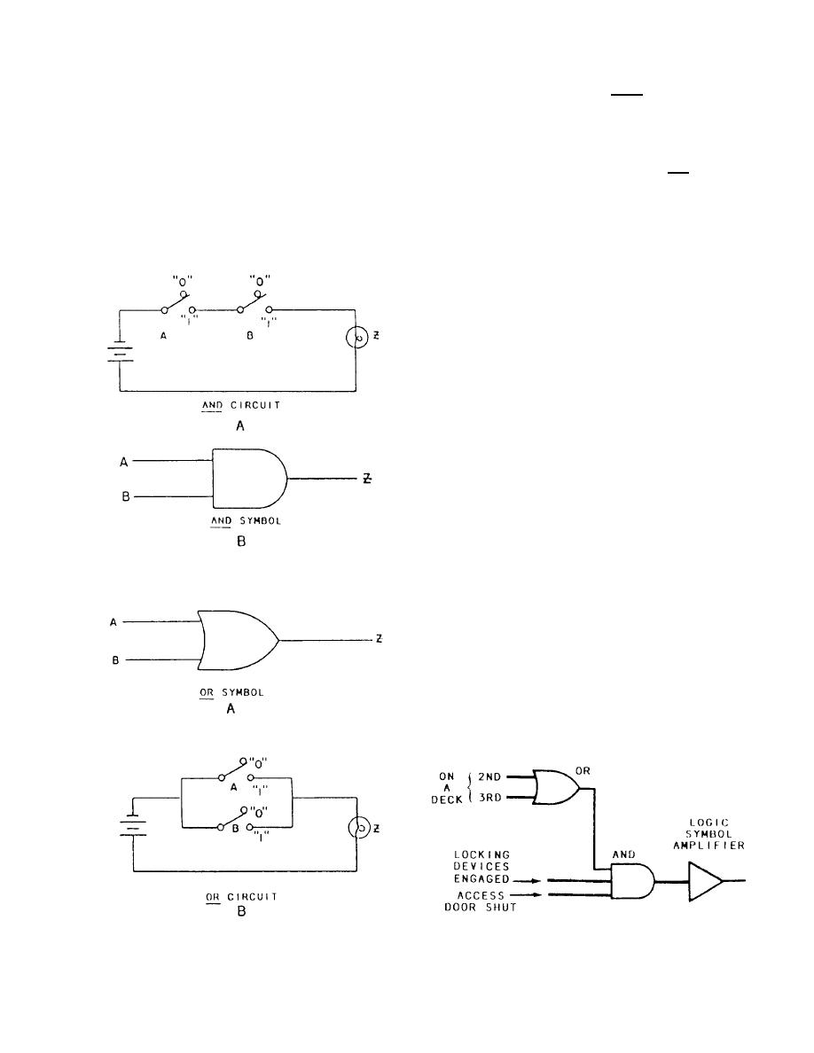 symbol is shown, which can be compared to the
starting and running magnetic contractors, an auto
transformer, a thermal overload relay, and a mercury
electrical circuit in figure 1-10, view B.
timer to control the duration of the starting cycle.
NOTE: Both switches, A AND B, must be closed
to energize the lamp.
Logic Controllers
In figure 1-11, view A, art OR symbol is shown,
Some of the controlled equipment that you will
which can be compared to the electrical circuit in fig-
encounter use logic systems for circuit control. For
ure 1-11, view B, where either switch A OR B needs to
additional information in this area the Navy Electricity
be closed to energize the lamp.
and Electronics Training Series (NEETS), module 13,
Using the characteristics of the AND and OR logic
is an excellent basic reference.
symbols, we will now discuss how they can be used in
The basic concept of logic circuits is shown in
a logic controller.
figures 1-10 and 1-11. In figure 1-10, view A, an AND
One common application of logic control that is
being incorporated on newer ships is the elevator
system. Since this system is large and consists of many
symbols, we will show only a small portion of this
system.
Let us assume that the elevator platform is on the
third deck and that you require it on the main deck--Refer
to figure 1-12. Three conditions must be met before the
elevator can be safely moved. These conditions are
detected by electronic sensors usually associated with
the driven component. One of the conditions is that the
platform must be on EITHER the second or third deck
(on a certain deck as opposed to somewhere in between).
If this condition is sensed, the OR symbol will have an
input, and since only one input is needed, the OR symbol
also will have an output.
Figure 1-10.-AND symbol and circuit.
The other two conditions to be met are that the
locking devices must be engaged and the access doors
must be shut. If the sensors are energized for these two
conditions, the AND symbol will have the three inputs
necessary to produce an output. This output will then set
up a starting circuit, allowing the motor to be started at
your final command.
The advantages of these electronic switches over
mechanical switches are low power consumption, no
moving parts, less maintenance, quicker response, and
Figure 1-11.-OR symbol and circuit.
Figure 1-12.-Basic logic circuit.
1-9
|
|
Privacy Statement - Press Release - Copyright Information. - Contact Us |
