 |
|||
|
Page Title:
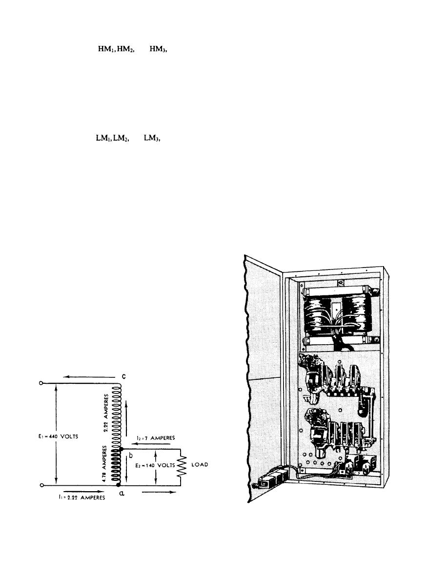
Figure 1-8.-Single-phase autotransformer. |
|
||
| ||||||||||
|
|
 coil remains energized after the push button is released,
than the source voltage can be obtained by tapping the
closing holding contacts HA. The coil, HM, also closes
proper point on the winding between terminals A and C.
and
applying full-
main line contacts
Some autotransformers are designed so a knob-
line voltage to the motor high-speed winding. The motor
controlled slider makes contact with wires of the
will run at high speed until coil HM is de-energized
winding to vary the load voltage.
either by opening the stop switch, a power failure, or an
overload.
The directions for current flow through the line,
transformer winding, and load are shown by the arrows
Pressing the low-speed push button closes the low-
in figure 1-8. Note that the line current is 2.22 amperes
speed contactor by energizing coil LM. The coil remains
and that this current also flows through the part of the
energized after the button is released, through the holdi-
winding between B and C. In the part of the winding that
ng coil contacts, LA. The coil, LM, also closes the
is between A and B, the load current of 7 amperes is
mainline contacts,
and
which apply the
opposed by the line current of 2.22 amperes. Therefore,
full-line voltage to the low-speed motor winding. The
the current through this section is equal to the difference
motor will run at low speed until coil LM is de-
between the load current and the line current. If you
energized. The LM and HM contractors are mechanically
subtract 2.22 amperes from 7 amperes, you will find the
interlocked to prevent both from closing at the same
secondary current is 4.78 amperes.
time.
Autotransformers are commonly used to start three-
phase induction and synchronous motors and to furnish
Autotransformer Controllers
variable voltage for test panels. Figure 1-9 shows an
autotransformer motor starter, which incorporates
A single-phase autotransformer has a tapped
winding on a laminated core. Normally, only one coil is
used on a core, but it is possible to have two auto-
transformer coils on the same core. Figure 1-8 shows
the connections for a single-phase autotransformer
being used to step down voltage. The winding between
A and B is common to both the primary and the second-
ary windings and carries a current that is equal to the
difference between the load current and the supply
current.
Any voltage applied to terminals A and C will be
uniformly distributed across the winding in proportion
to the number of turns. Therefore, any voltage that is less
Figure 1-8.-Single-phase autotransformer.
Figure 1-9.-Autotransformer controller.
1-8
|
|
Privacy Statement - Press Release - Copyright Information. - Contact Us |
