 |
|||
|
Page Title:
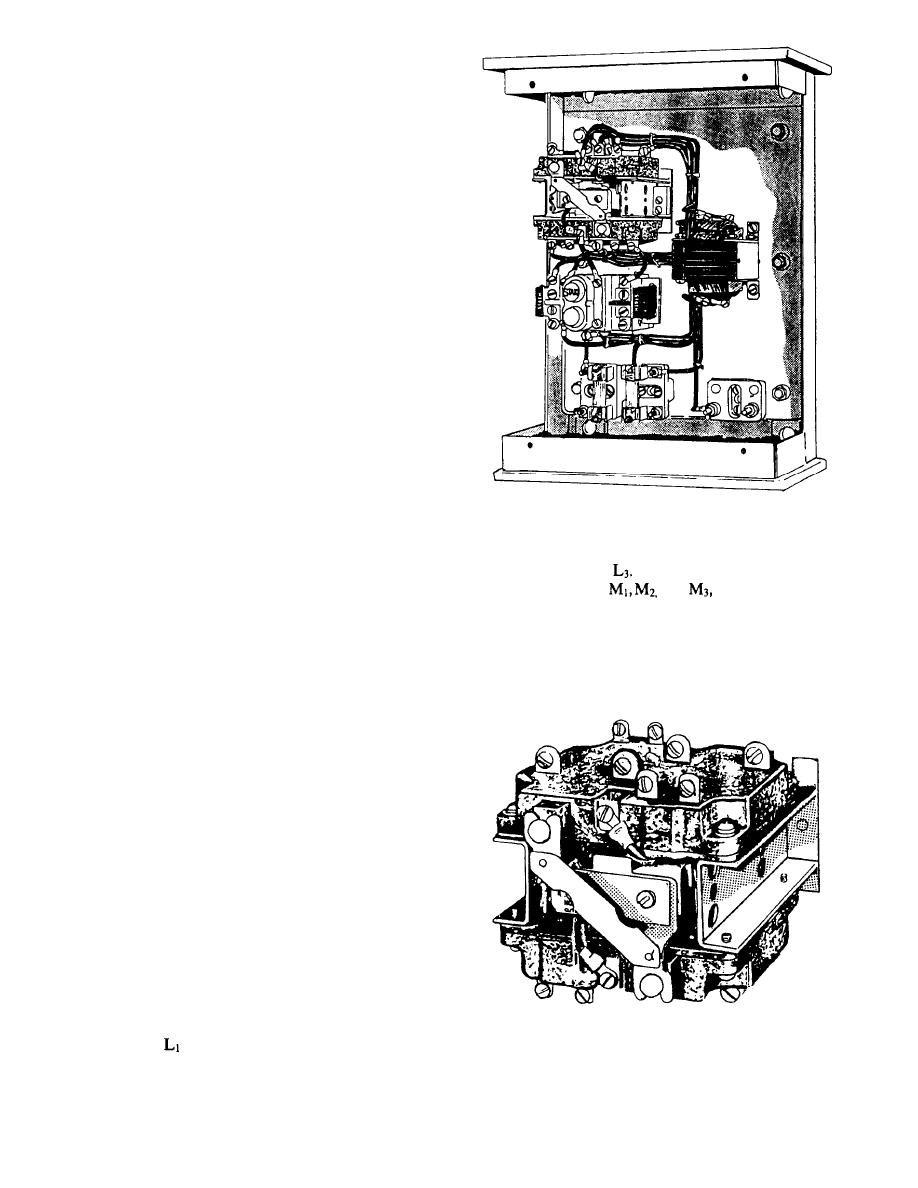
Figure 1-4.-Across-line, 3-phase controller. |
|
||
| ||||||||||
|
|
 but the circuit breaker rating is too high to protect each
motor separately.
Short-circuit protection for control circuits is
provided by fuses in the controller enclosure, which
provides protection for remote push buttons and
pressure switches.
FULL-FIELD PROTECTION
Full-field protection is required in the controller for
a dc motor when a shunt field rheostat or a resistor is
used to weaken the motor field and obtain motor speeds
more than 150 percent of the speed at rated field current.
Full-field protection is provided automatically by a relay
that shunts out the shunt field rheostat for the initial
acceleration of the motor, and then cuts it into the motor
field circuit. In this way, the motor first accelerates to
100 percent or full-field speed, and then further
accelerates to the weakened-field speed determined by
the rheostat settings.
The controller for an anchor windlass motor
provides stepback protection by automatically cutting
back motor speed to relieve the motor of excessive load.
Figure 1-4.-Across-line, 3-phase controller.
LOW-VOLTAGE RELEASE (LVR)
contactor coil, M to
When the coil is energized, it
When the supply voltage is reduced or lost
closes line contacts
and
which connect the
altogether, an LVR controller disconnects the motor
full-line voltage to the motor. The line contactor
from the power supply, keeps it disconnected until the
auxiliary contact, MA, also closes and completes a hold-
supply voltage returns to normal, and then automatically
ing circuit for energizing the coil circuit after the start
restarts the motor. This type of controller is equipped
push button has been released.
with a maintaining master switch.
LOW-VOLTAGE PROTECTION (LVP)
When the supply voltage to an LVP controller is
reduced or lost, the motor is disconnected from the line.
Upon restoration of power, the motor will not start until
you manually depress the start push button.
MAGNETIC ACROSS-LINE
CONTROLLERS
A typical 3-phase, across-line controller is shown in
figure 1-4. Figure 1-5 shows a small cubical contactor
for a 5-horsepower motor. All contractors are similar in
appearance, but they vary in size.
An elementary or schematic diagram of a magnetic
controller is shown in figure 1-2. The motor is started
by pushing tie strut button. The action completes the
circuit from
through the control fuse, stop button,
Figure 1-5.-Contactor for a 5-horsepower motor.
start button, the overload relay contacts, OL, and the
1-6
|
|
Privacy Statement - Press Release - Copyright Information. - Contact Us |