 |
|||
|
Page Title:
Figure 1-1.-Schematic of controller with emergency run push button. |
|
||
| ||||||||||
|
|
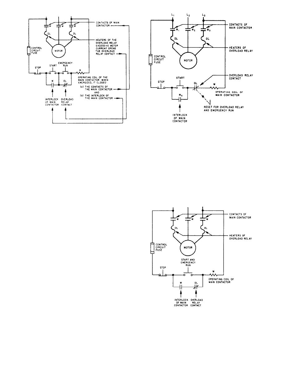 Figure 1-2.-Schematic of controller with reset-emergency run
Figure 1-1.-Schematic of controller with emergency run push
lever or rod.
button.
short circuits in motor controllers is obtained through
emergency run operation, the operator must hold down
this push button and press the START button to start the
other devices. To protect against these short circuits,
motor. While the emergency run push button is
circuit breakers are installed in the power supply system,
depressed, the motor cannot be stopped by opening the
thereby protecting the controller, motor, and cables.
overload relay contact.
Short-circuit protection is provided in controllers where
A REST-EMERGENCY RUN lever is shown in
it is not otherwise provided by the power distribution
figure 1-2. As long as the lever or rod is held down, the
system or where two or more motors are supplied power
overload relay contact is closed. The start button must
be momentarily closed to start the motor. Figure 1-3
shows a START-EMERGENCY RUN pushbutton. The
motor starts when the button is pushed, and it continues
to run without overload protection as long as it is held
down. For this reason, push buttons that are marked
start-emergency run should not be kept closed for more
than a second or two unless the emergency run operation
is desired.
Manual controllers also may be provided with an
emergency run feature. The usual means is a start-
emergency run push button or lever, which keeps the
main contactor coil energized despite the tripping action
of the overload relay mechanism.
SHORT-CIRCUIT PROTECTION
Overload relays and contractors are usually not
designed to protect motors from currents greater than
about six times normal rated current of ac motors or four
Figure 1-3-Schematic of controller with start-emergency run
times normal rated current of dc motors. Since short-
push button.
circuited currents are much higher, protection against
1-5
|
|
Privacy Statement - Press Release - Copyright Information. - Contact Us |
