 |
|||
|
|
|||
| ||||||||||
|
|
 The operation of the salinity indicator system is
(ppm); the terms are interchangeable. For purposes of
our discussion, we will use epm. The system is a neces-
based on the principle that an increase of the electrolytic
sity aboard ship because all fresh water, particularly
impurities (principally salt) in water increases the elec-
when underway, is made from seawater. Excessive
trical conductivity of the water and, conversely, that a
decrease in the impurities increases the electrical resis-
salinity in the boiler feedwater causes pitting of the
tubes and rapid deterioration due to electrolysis. Salin-
tance of the water. If two electrodes are immersed in the
water tested and a stable alternating voltage is applied
ity indicators are usually provided in the engine rooms
across the electrodes, a stable alternating current will
and the firerooms for checking the condensate from the
flow, provided the impurity content and the temperature
main and auxiliary condensers. They are also provided
of the water remain unchanged.
for the evaporator plants to indicate the degree of purity
The amount of current flow is indicated on a meter,
of the fresh water and condensate at various selected
the scale of which is graduated in equivalent parts per
points in the distilling system.
million. If the saline content of the water increases
The ship's water system (fig. 10-39) pumps water
because salt water leaks into the system or because the
aboard the ship from the sea, sends it through the
operation of the distilling plant becomes faulty, the
evaporator to remove the salt, and then stores the puri-
conductivity between the electrodes increases and the
fied water in freshwater tanks. The fresh water is used
meter reading increases an amount that is proportional
for showers, drinking water, cooking, and, most impor-
to the increase in salinity.
tantly, it is used in the ship's boilers to generate the
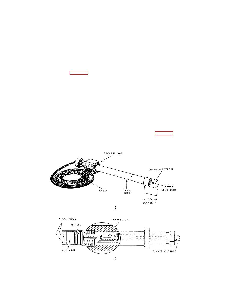
The salinity system is composed of three major
steam that drives the ship. The boiler feedwater must
components: the salinity cell, the salinity indicator
contain less than 0.065 epm or the boilers can be dam-
panel, and the dump valve and solenoid.
aged or "salted up." The salinity system monitors the
impurity content continuously; should the impurities
Salinity Cell
reach alarm proportions, the salinity system de-ener-
gizes the dump valve solenoid and redirects the
contaminated water to the ship's bilge or directly over-
The salinity cell (fig. 10-40, views A and B) is the
board.
device that does the actual detecting of impurity. It
|
|
Privacy Statement - Press Release - Copyright Information. - Contact Us |
