 |
|||
|
Page Title:
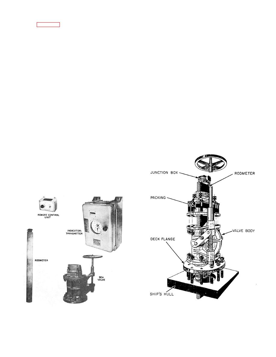
Figure 10-35.--Major components of an underwater log system. |
|
||
| ||||||||||
|
|
 slightly above the ON speed value in a decreasing
the exact scale zero because a limiting switch (not
direction because of the operating differential
shown in fig. 10-34) de-energizes synchronous motor
inherent in microswitch 200.
4 at a pointer indicator of approximately 1 rpm.
The full-scale indication should occur when the
Indicators
point of roller contact is exactly 1 inch from the
center of disk 30. The indicators provide for an
Indicators are installed in the pilothouse and
overspeed indication of about 10 percent above full
engine rooms to indicate the rpm of the associated
scale (1.10 inches disk radius) before limit switch 70
propeller shaft. An indicator consists of a positioning
is actuated.
synchro receiver and a revolving pointer that
indicates on a dial the rpm of the associated propeller
The indicator-transmitter can be provided with
shaft. The synchro receiver is driven by the
speed signal switch 200 to continuously energize a
positioning synchro transmitter in the associated
remote light or other signal at propeller speeds below
indicator-transmitter unit. The indicator is also
a specified value. The signal setting is adjustable
provided with a backing signal that is energized by
from about one-quarter of full speed down to about 5
the unidirectional mechanism in the shaft
rpm. As the speed of the propeller shaft decreases
transmitter when the propeller shaft rotates in the
from higher value above the switch operating point,
reverse direction.
yoke 15, bracket 205, and actuator screw 204 are
advanced along lead screw 16, until the roller and
UNDERWATER LOG SYSTEM
arm of stationary single-pole, double-throw (SPDT)
switch 200 are lifted by actuator screw 204. The
The underwater log system (circuit Y) measures
speed value at which the switch is operated is
and indicates the speed of the ship in knots and the
determined by the height of actuator screw 204,
distance traveled through the water in nautical miles.
above bracket 205. The speed signal switch is
adjusted by turning the actuator screw until the
desired operating point is obtained. After the switch
has been actuated in decreasing speed direction, it
will remain actuated at lower speeds down to zero.
Also, when the propeller speed increases, the OFF
or release point of the switch will occur at a value
140.158
and packing assembly with the rodmeter
underwater log system.
installed.
|
|
Privacy Statement - Press Release - Copyright Information. - Contact Us |
