 |
|||
|
Page Title:
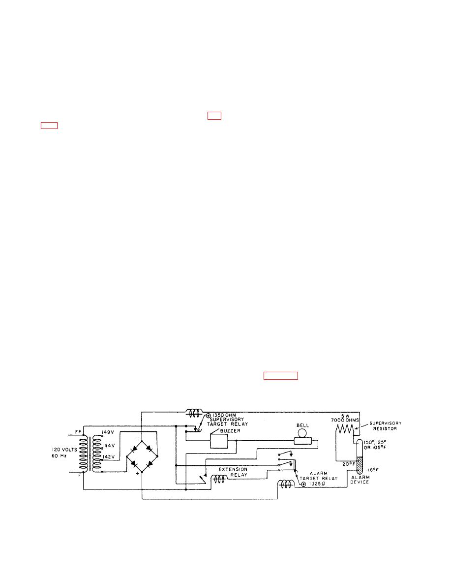
Figure 9-16.--High-temperature alarm circuit. |
|
||
| ||||||||||
|
|
 armature is located directly in front of the coil and is
supervisory drum shows a yellow section when it is
hinged between the side members of the frame. An
de-energized. The two relays are in series with a
insulated roller attached to the upper pm-t of the armat-
sensing device.
ure engages the contact spring. A helical coil spring
When the circuit is in normal operation, the
maintains the armature in the open position when the
supervisory relay is energized. The supervisory
coil is de-energized. The contacts are open when the coil
resistor (a 7000-ohm, 5-watt resistor, connected
is de-energized or in a normal condition, and closed
across the terminals of the last sensor or detector)
when energized or in an alarm condition.
associated with the contact maker is in the circuit.
The indicator drum is located in front of the arma-
While the alarm relay is also in the circuit, it is not
ture and is pivoted between the sides of the frame (fig.
sufficiently energized to operate the armature and
close the contacts. When a contact maker closes, it
link, and rotates when the armature operates. The face
short-circuits the supervisory resistor for that circuit,
of the drum protrudes slightly through the panel to be
causing an increase in current. This increase in current
visible. The part of the drum visible when operated is
increases the magnetic energy of the alarm relay to a
painted red, the rest of the drum is grey.
point where it will operate its armature, closing the
The supervisory relay is similar in design and con-
alarm relay contacts, energizing the alarm bell. When
struction to the alarm relay. However, the number of
the alarm relay operates, it also rotates the target drum
turns on the coils and the contact arrangement are
to red, indicating the circuit is in an alarm condition.
different. The supervisory relay is equipped with one
pair of contacts. Note that when the armature (1) of the
Since the normal operating current is just
alarm relay operates, it rotates the target drum (5)
sufficient to hold the supervisory relay armature
through an eccentric, and closes the contacts for the
operated, an open circuit will cause the supervisory
audible alarms by moving the roller (3). However, the
relay to drop out. This, in turn, closes the supervisory
supervisory-target relay is designed to be normally op-
contacts, energizing a buzzer and rotating the
erated; its alarm contact is closed when the relay is
supervisory target drum to yellow, indicating the
de-energized, and open when energized.
circuit with a problem.
The magnetic coil of the supervisory relay is wound
The current flowing under normal conditions
with 14,500 turns of wire and has a resistance of 1350
(supervisory relay operated, supervisory resistor in the
ohms.
circuit, alarm relay not operated) is approximately
The line unit test switch is a three-position, four-
0.012 amperes. If a contact maker closes, shunting the
pole, rotary switch. The switch is not adjustable and
supervisory resistor, the current flow will rise to
should require no maintenance.
approximately 0.043 amperes, which is sufficient to
operate the alarm relay.
Normal Operation
An extension signal relay is also in the alarm
circuit (fig. 9-16). When the alarm relay contacts
The alarm drum has a red section that rolls into
view when the alarm-target relay is operated. The
close, the alarm bell is energized by the extension
9-14
|
|
Privacy Statement - Press Release - Copyright Information. - Contact Us |