 |
|||
|
Page Title:
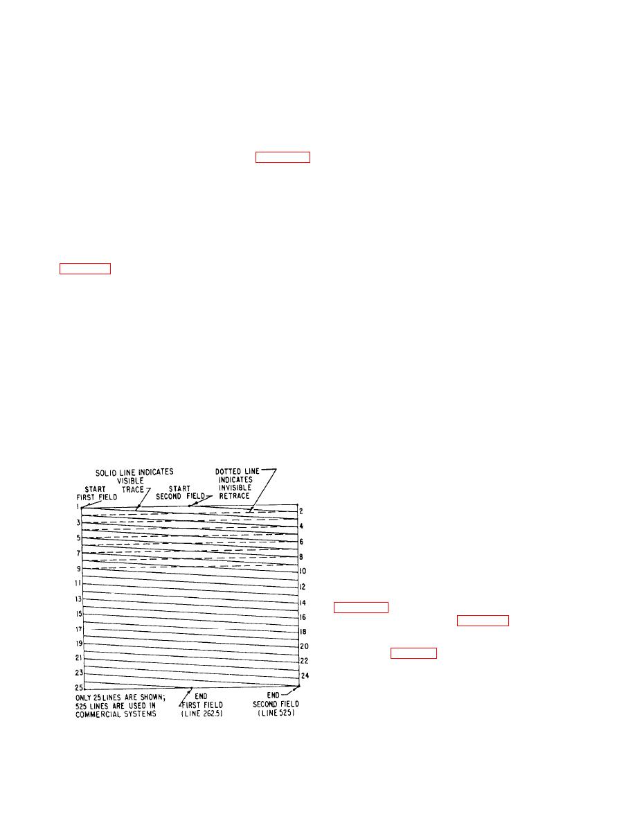
Figure 8-6.--Interlaced scanning. |
|
||
| ||||||||||
|
|
 returned to the beginning of line 1, and the whole
In television, similar problems are encountered.
process is repeated.
To keep flicker from becoming objectionable, 30
complete frames per second are shown. Flicker is
Synchronizing and blanking signals are trans-
further reduced by interlaced scanning. This has
mitted by the transmitter to keep the movement of the
essentially the same effect as increasing the frame
electron beams in the camera and picture tube in step.
frequency to 60 frames per second. The horizontal
These signals also blank out the signals from the
scanning speed and bandpass requirements of the
picture tube during the horizontal and vertical retrace
composite TV signal remain the same.
periods.
Interlaced scanning is illustrated in figure 8-6.
Sequential scanning differs from interlace
Bandpass considerations, the problems of synchro-
scanning in the method of moving the electron beam
nization, and the necessity for detail lead to the choice
down the screen. The sequential system can be
of 525 horizontal scanning lines per frame. To reduce
compared to reading a page of print. Each line is read
flicker by interlaced scanning, the electron beam scans
in turn instead of every other line as in interlace
the odd-numbered lines first and then the even-
scanning.
numbered lines. Thus, two scans (fields) are necessary
If 60 complete frames are scanned per second,
to complete one frame. For example, as shown in
flicker does not exist. However, unless the system has
a very broad bandpass, resolution would decrease due
left side of line 1. The beam moves across the image
to the high video frequencies (extremely fast changing
plate at a slight downward angle (pulled downward by
current levels through the load resistor) being
the vertical deflection coils). At the end of the line, the
produced. The horizontal scanning speed would have
electron beam is blanked out during the retrace to the
to be doubled and would introduce other problems
left side of line 3. This process is continued until the
with extremely high frequencies.
middle of line 525 is reached. Therefore, 262.5 lines
are scanned in the first field. When the beam reaches
COMPOSITE SIGNAL
the middle of the last line, it is blanked out and
returned to the middle of line 2 where the trace for the
Blanking signals are used in both the camera tube
second field starts. The even-numbered lines are
and the picture tube control circuits. These signals cut
scanned in sequence until the end of line 524 is
off the electron beam at the end of a horizontal scan
reached. At that instant the beam is blanked out and
line so that the return trace does not produce picture
signals at the transmitter or receiver picture tube.
Blanking signals are also used to cut off the vertical
return trace following the scan of each field.
Superimposed on the blanking signals are the
synchronizing signals. These signals trigger the
vertical sweep circuits and synchronize the horizontal
sweep circuits of the receiver/monitor. The horizontal
sync signals trigger the horizontal sweep at the correct
instant 15,750 times per second (the horizontal sweep
frequency). The vertical sync signals trigger the
vertical sweep at the correct instant 60 times a second.
the scanning illustrated in figure 8-6.
The vertical sync pulses have a special serrated
form (see fig. 8-8) preceded and followed by
equalizing pulses to produce interlaced scanning. This
also keeps the horizontal sweep locked in step during
the vertical retrace period.
All television receivers must perform basically the
same functions. They must select the desired carrier
frequency. They must amplify the required band of
8-10
|
|
Privacy Statement - Press Release - Copyright Information. - Contact Us |