 |
|||
|
|
|||
| ||||||||||
|
|
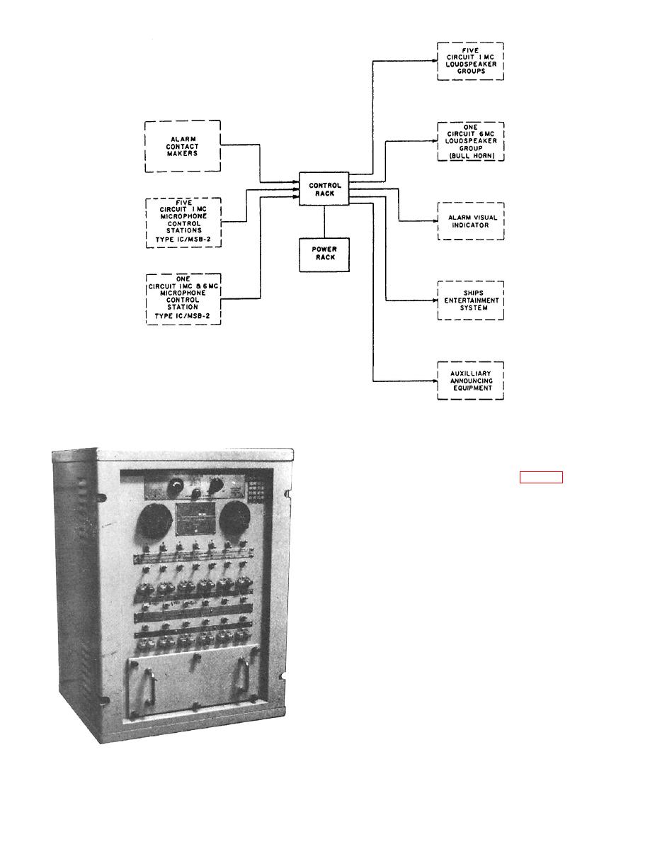 CONTROL RACK
The control rack (fig. 7-9) is a
bulkh ead-mou n ted enc losu r e c on tain in g the
pr eamplifier modules, power supply modules,
osc illator alar m modules, and the sy stem
switc h ing and tr ansfer r in g c on tr ols and
indic ator s. The r ac k also c on tain s the c on tr ol
and power r elay s, the r elay power supply , and
the terminal boards for making connections to
the ship' s w ir in g .
The control rack preamplifier voice and
alarm signals from the microphone control
stations, routes them to the power rack for
amplification, and then transmits them to the
various loudspeaker groups.
Preamplifier Modules
Two preamplifier modules are located in
the control rack one for each amplifier channel.
Each preamplifier contains four transistor-
amplifier stages for increasing the low-level
7.176
microphone and alarm signals to drive
7-10
|
|
Privacy Statement - Press Release - Copyright Information. - Contact Us |
