 |
|||
|
Page Title:
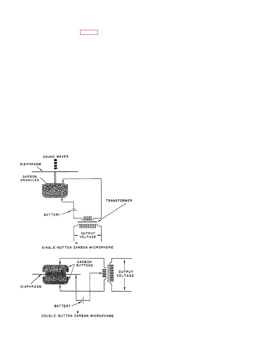
Figure 7-4.--Schematic diagram of a carbon microphone. |
|
||
| ||||||||||
|
|
 secondary turns and also upon the change in primary
Carbon Microphone
current. Normal output voltage of a typical circuit is
from 3 to 10 volts peak at the secondary terminals.
The carbon microphone (fig. 7-4) operates on the
principle that a changing pressure of a diaphragm
The carbon microphone is not used in shipboard
applied to a small volume of carbon granules changes
announcing equipment because it requires a polarizing
its electrical resistance according to the vibrations of the
current and has a tendency to amplify certain
sound waves striking the diaphragm.
frequencies more than others.
The carbon microphone consists of a diaphragm
Characteristics of Microphones
mounted against a mass of carbon granules that are
contained in a small cup. To produce an output voltage,
Microphones are rated according to their (1)
this microphone is connected in a series circuit
frequency response, (2) impedance, and (3) sensitivity.
containing a battery and the primary of a transformer.
FREQUENCY RESPONSE.-- Shipboard an-
When a direct current follows through the carbon
nouncing and intercommunicating systems are designed
granules, the varying resistance changes the amplitude
to produce maximum speech intelligibility under
of the current and produces an alternating voltage in the
conditions of high background noise. To achieve this
secondary of the transformer. This voltage has the same
objective, the overall frequency response characteristic
waveform as the sound waves striking the diaphragm.
of the system is altered by cutting off the system
The current through this microphone may be as great as
response at some lower limit, such as 500 Hz, and by
0.1 ampere. The resistance may vary from about 50 to
employing an emphasized frequency response
90 ohms. The voltage developed across the secondary
characteristic that rises with increasing frequency at a
depends upon the ratio of the transformer primary and
rate of approximately 6 dB per octave. The output sound
pressure is doubled each time the frequency is doubled
for a constant level input to the system. The emphasized
speech tends to sound thin and sometimes harsh, but
when the masking due to background noise is almost as
high as the speech level, the speech appears to cut
through the noise.
For good quality, a microphone must convert sound
waves into electrical waves that have the same relative
magnitude and frequency without introducing any new
frequencies. The frequency range of the microphone
must be at least as wide as the desired overall response
limits of the system with which it is used.
Except in the case of the emphasized system in
which it may be desirable for the microphone to have a
rising frequency-response characteristic, the micro-
phone response should be uniform or flat, within its
frequency range, and free from sharp peaks or dips, such
as those caused by mechanical resonances.
IMPEDANCE.-- Crystal microphones have
impedances of several hundred thousand ohms, whereas
the magnetic and dynamic microphones have
impedances that range from 20 to 600 ohms. The
impedance of a microphone is usually measured
between its terminals at some arbitrary frequency within
the useful range, such as 1000 Hz.
The impedance of magnetic and dynamic
microphones varies with frequency in much the same
manner as that of any coil or inductance; that is, the
|
|
Privacy Statement - Press Release - Copyright Information. - Contact Us |
