 |
|||
|
Page Title:
Table 6-11.--Controls and Indicators for the Current Flow Test |
|
||
| ||||||||||
|
|
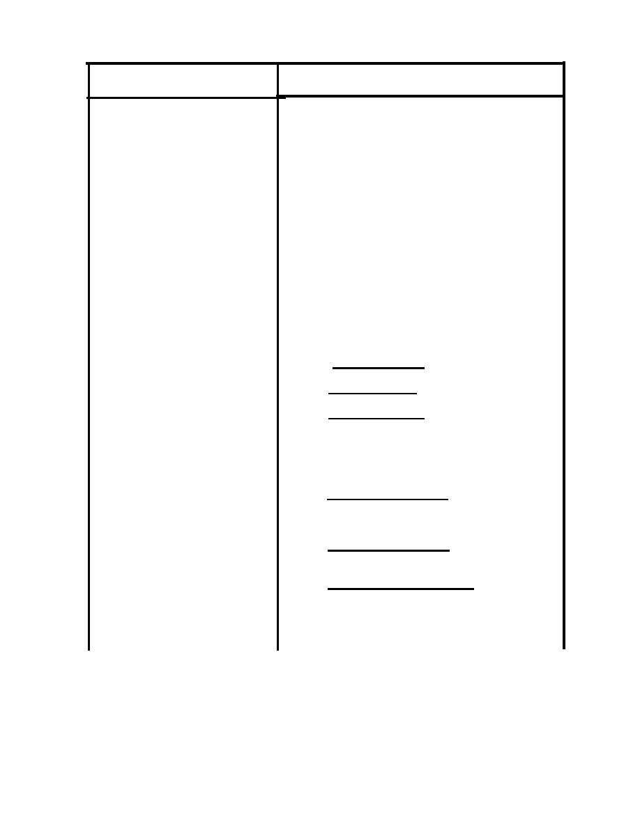 FUNCTION
CONTROL OR INDICATOR
RH-1 through RH-4
Variable resistors; provide fine
adjustment of current for each of the
four resistance circuits.
SW-1 through SW-4
Selector switches; provide coarse
control of current in each of the four
resistance circuits.
Push switches; complete the associated
K-1 through K-4
resistance circuits, which are associ-
ated as follows:
K-1
-
RH-1
and
SW-1
K-2
-
RH-2
and
SW-2
K-3
-
RH-3
and
SW-3
K-4
-
RH-4
and
SW-4
Lever switch; controls application of
BAT CONTROL
battery to binding posts.
In OFF position - removes battery
from binding posts.
In ON position - applies battery to
binding posts.
In REV position - reverses polarity
of battery to binding posts.
Lever switch; selects proper operate
RELAY SWITCH
mode for type of relay winding condi-
tion.
In NEG RLY position - for testing
relays having either battery con-
nected to one terminal or no
potential present.
In POS RLY position - for testing
relays having external ground con-
nected to one terminal.
In POS NEG RLY position - for
testing dual-coil relays, having
external battery connected to
terminal of one coil and external
ground to terminal of other coil.
|
|
Privacy Statement - Press Release - Copyright Information. - Contact Us |
