 |
|||
|
Page Title:
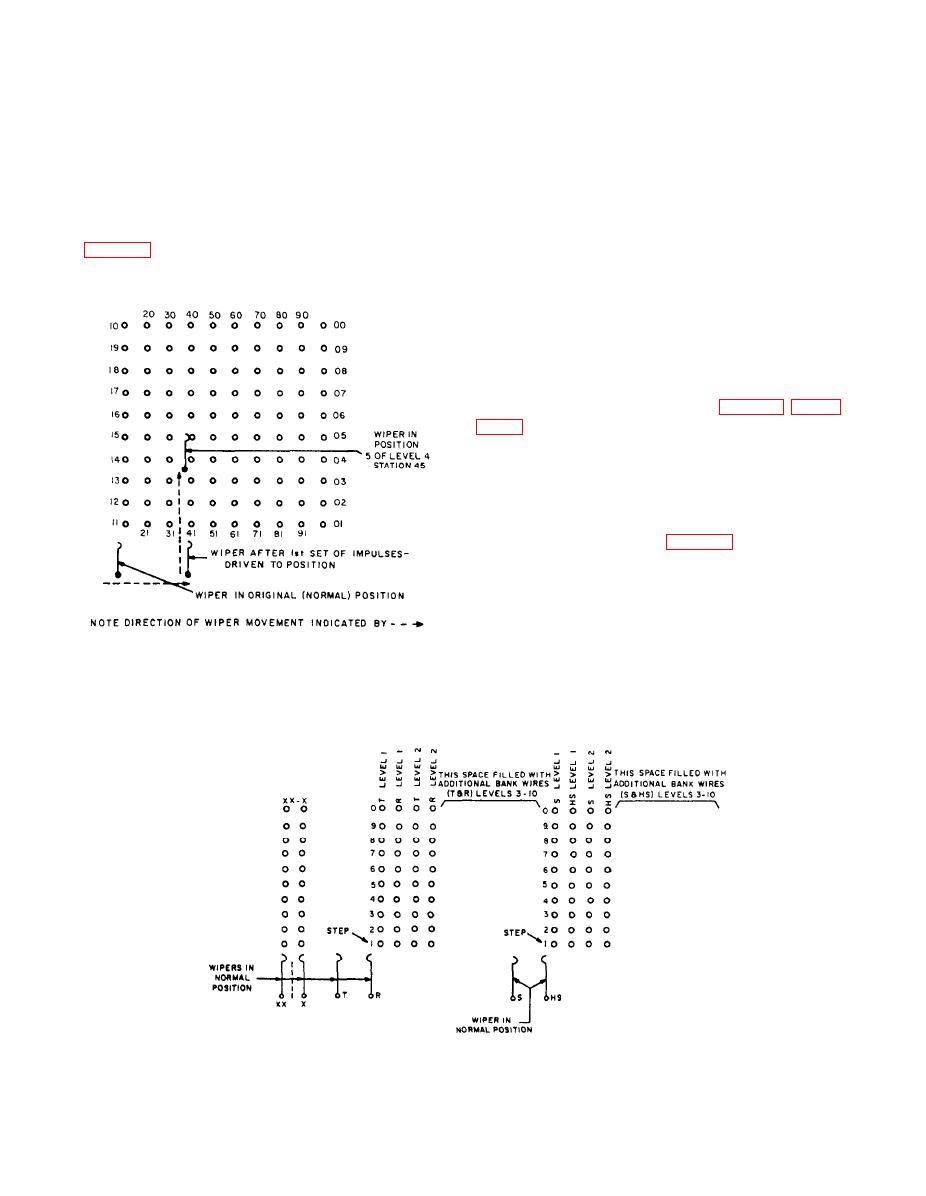
Figure 6-33.--Four wire banks and associated wipers shown in the normal position. |
|
||
| ||||||||||
|
|
 wipers to return to the normal position. The release
supervisory and control functions. When the wipers
springs are operated to release the external control
are stepped in the X direction, the X-off normal
circuitry. The release magnet restores when both the
springs are operated; when stepped in the Y direction,
X- and Y-off normal springs return to normal.
the Y-off normal springs are operated. Only 10 steps
are allowed in either direction. If these are exceeded,
THE WIRE BANK.-- The 42- by 10-wire bank
the overflow springs are operated. When the X-off
associated with the XY switch is actually made up of
normal or Y-off normal springs are operated, a path is
six smaller wire banks: four 10- by 10-wire banks and
competed to the release magnet. A ground (signal)
two 1- by 10-wire banks. The 10- by 10-wire banks
can then be extended to pin 29 of the XY switch plug
are used with the four wires associated with each
telephone line. These four wires are the tip (T) and
ring (R) for transmission, and sleeve (S) and helping
sleeve (HS) for supervisory and switching. The 1- and
10-wire banks (XX and X) are used to electrically
indicate the X position of the wipers when the wipers
are stepped in the X direction. Each of these banks is
associated with its own particular wiper on the XY
switch. The switch wipers are referred to as the T, R,
S, HS, and XX-X wipers or banks (fig. 6-31). Figure
10-wire banks (as seen from above) and the associated
wiper.
This wire bank runs the length of the switchboard
and is associated with the same wiper in all the other
XY switches in the system (fig. 6-33). The X motion
of the switch locates the wiper at a position (or bank)
opposite the proper section of the wire bank referred
to as the level. The Y motion of the switch positions
the wiper into the bank to establish the connection at
the proper point. The switch then remains in position
indefinitely until it is released. A terminal block at the
simplified schematic diagram.
end of the wire bank provides the necessary
6-37
|
|
Privacy Statement - Press Release - Copyright Information. - Contact Us |
