 |
|||
|
Page Title:
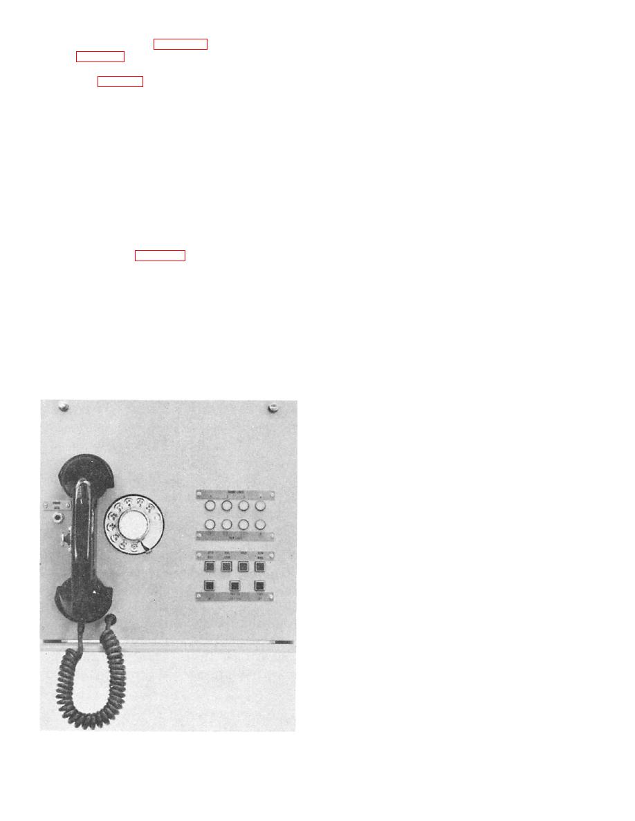
Figure 6-28.--Attendant's console. |
|
||
| ||||||||||
|
|
 switchboard cabinets (fig. 6-27). An attendant's
COMMON CONTROL PANEL (100 ASSEM-
cabinet (fig. 6-28) provides an interface between ship
BLY).-- The common control assembly consists of six
lines and shore installations when the ship is in port,
separate, though related, circuits. The main function
as shown in (fig. 6-26).
of the 100 assembly is to provide timing for finder
action requests and to extend finder request ground
Each cabinet (system or switchboard) consists of
(positive signal voltage) to the finder allotter. This
one rack of equipment shock-mounted in a rigid
assembly also provides dial tone and busy tone for the
cabinet assembly. The cabinet circuit modules,
system.
accessible through front and rear doors, plug into the
framejack panel and contain all the switching circuits
LEVEL
DETECTOR
AND
ALARM
necessary for system operation. Two XY universal
switches are associated with each of the 15
detector panel contains 10 identical level detection
finder/connector circuit modules used in each
circuits, one for each system level, and a portion of
switchboard cabinet. These switches mount in cells
the major and minor alarm circuits. The function of
located on the front of the frame and plug into the
the level detector is to receive negative battery signal
associated finder/connector circuit modules. The line
via a closed tip/ring loop of the line station requesting
connection panels are mounted directly to the
service; to operate the appropriate level relay; and to
switchboard frame (fig. 6-27). These panels provide
extend resistance battery to the sleeve wire bank and
the means for connecting the switchboard to the
a finder request ground to initiate linefinding for that
ship's cables. Screw-type terminals are provided for
level (group).
all connections, allowing line-number changes to be
readily accomplished.
FINDER ALLOTTER PANEL (300 ASSEM-
BLY).-- The finder allotter panel, also referred
Main Assemblies of the Switchboard Cabinet
to as the link allotter, contains 15 identical
circuits, one for each finder circuit and a finder
There are nine main assemblies in the MDM
bypass relay for each finder. The circuit is used
200/700 system. Each has both a name and a number
to select the next idle finder in the system. If the
designation.
selected finder takes longer than 2 seconds to
find the calling line, a finder bypass alarm is
initiated.
FINDER/CONNECTOR PANEL (400 AS-
SEMBLY).-- The finder/connector panel, also
referred to as a link, is made up of two main
sections: the finder circuit, where linefinding is
accomplished by the finder XY switch; and the
connector circuit where connection to the calling
line is accomplished by the connector XY switch.
The XY switch is external, but is part of the
link. The transmission path is established in the
assembly between the calling and the called
telephones.
SWITCHBOARD MONITOR PANEL (500
ASSEMBLY).-- The switchboard monitor panel
contains three alarm signaling circuits that
react to an off-hook alarm, a failure-to-restore
alarm, and a finder bypass alarm. The link index
switch determines the alarm condition. The
panel also contains a line test jack, two
functional lever switches, and eight indicator
lamps. This panel activates audible as well as
visual alarms.
LINE PANEL (600 ASSEMBLY).-- There are 10
line panels in each switchboard cabinet. Each panel
140.164
provides connections and switching facilities for one
level (group) of 10 telephones. The line disconnect
|
|
Privacy Statement - Press Release - Copyright Information. - Contact Us |