 |
|||
|
Page Title:
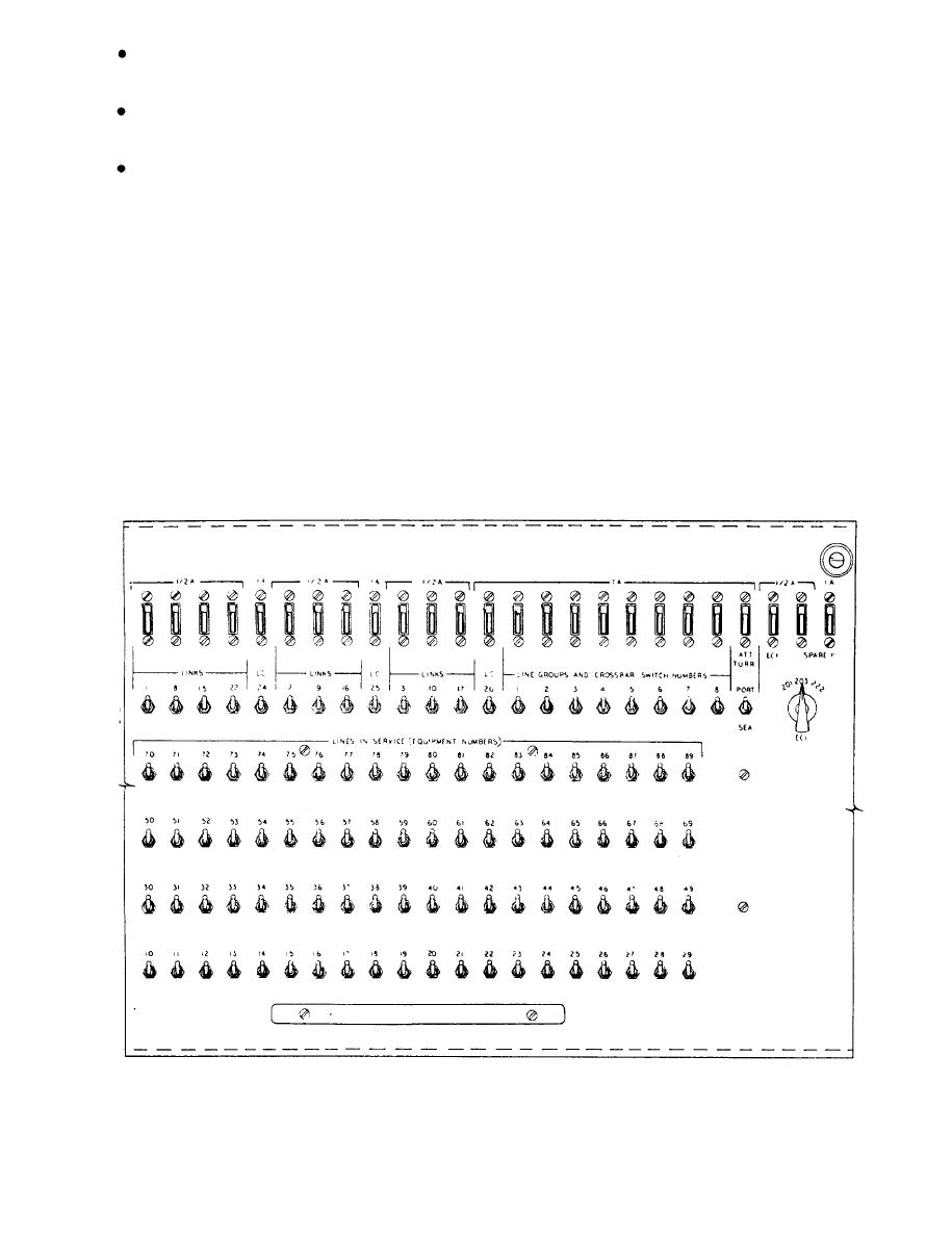
Figure 6-19.--Switch and fuse panel for the 100-line switchboard, cabinet 1. |
|
||
| ||||||||||
|
|
 contains equipment gates, the power supply, two
Provide "hunt-the-not-busy-line" service
ringing generators, and aground fault detection panel.
where required.
The rear section of both cabinets contains the rest of
Provide "emergency cut-in" service to line sta-
the crossbar switches. For the 100-line switchboard,
tions as specified.
seven switches are mounted in the rear section of
cabinet 1 and two switches are mounted in the rear
Disconnect the calling and called stations at the
section of cabinet 2. For the 150-line switchboard.
completion of the conversation.
seven switches are mounted in the rear section of each
cabinet. The rear panel of each cabinet is removable
Any two-wire, dial telephone set using break-type
to facilitate access to the rear section and the crossbar
dialing can be used with the system.
switches.
Switchboard Equipment
EQUIPMENT GATES.-- There are two equip-
Description
ment gates in each switchboard cabinet. The upper gate
in each cabinet mounts the switch and fuse panel for the
respective cabinet. The lower gate mounts the circuit
The automatic switching equipment is housed in
card cage. All the equipment gates swing out, providing
two dripproof, steel, shock-mounted cabinets. Each
access to the crossbar switches mounted in the rear of
cabinet has a front section and a rear section. The front
each cabinet in the event the rear panel cannot be
section of cabinet 1 contains equipment gates and one
removed. This swing-out feature also provides access
crossbar switch. The front section of cabinet 2
|
|
Privacy Statement - Press Release - Copyright Information. - Contact Us |