 |
|||
|
Page Title:
Figure 6-13.--Schematic diagram of the type G (version 2) telephone set. |
|
||
| ||||||||||
|
|
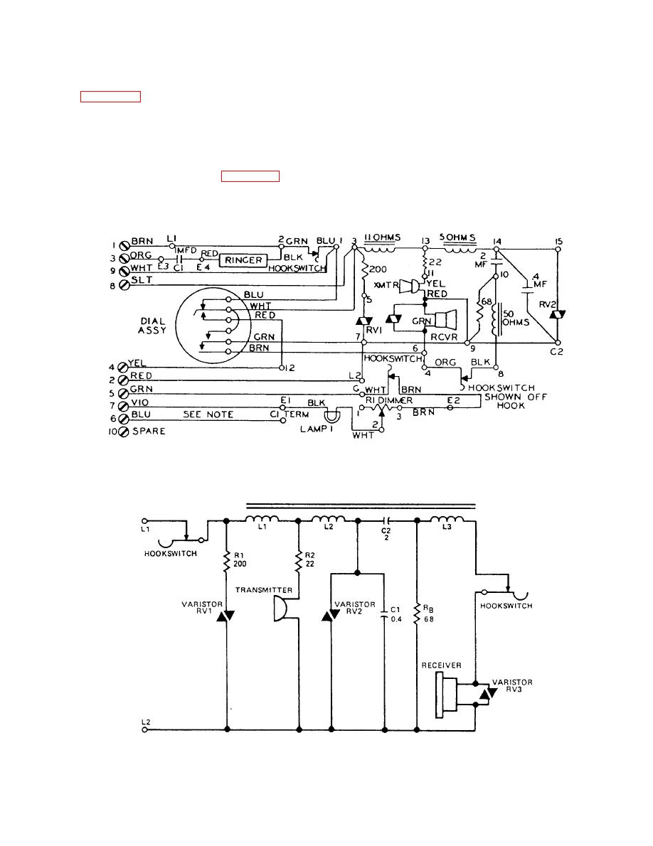 you press this button, the handset will be released from
circuit. This circuit serves the same function as the
its cradle.
transmission network circuit in the version 1 set.
When you remove the handset from its cradle, three
Internal Circuitry
paths for dc are provided from terminal L1 to terminal
L2. Dc path 1 is through resistor RI and varistor RV1.
Dc path 2 is through inductor L1, resistor R2, and the
(version 2) telephone set. The circuit is designed and
transmitter. Dc path 3 is through inductors L1 and L2
operates in a slightly different manner as that of the
and varistor RV2.
version 1 set. Circuit operation will be discussed in the
The mutual inductance of inductors L1, L2, and
following paragraphs.
L3 and the value of resistor RB (resistor, balance 68
ohms) is such that a comfortable level of sidetone is
plified schematic diagram of the network assembly
heard in the receiver when the transmitter is excited.
|
|
Privacy Statement - Press Release - Copyright Information. - Contact Us |
