 |
|||
|
Page Title:
Figure 6-5.--Schematic diagram of the type G (version 1) telephone set |
|
||
| ||||||||||
|
|
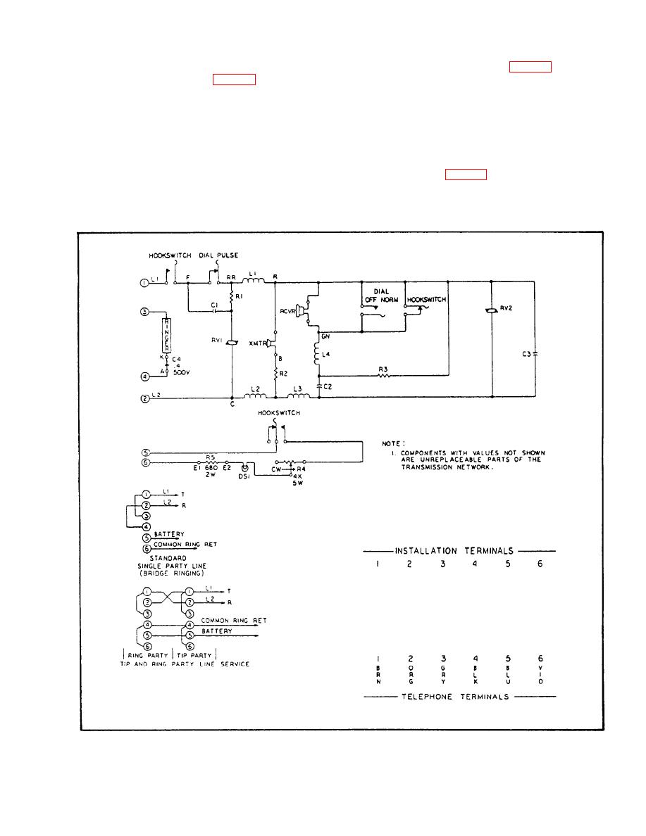 RINGER.-- A gong and clapper-type ringer is
control, which is an adjusting screw. By using a
screwdriver, you can access the dimmer control
used in the telephone set to alert personnel of an
through a cutout provided in the cover. The lamp and
incoming call. The ringer circuit (fig. 6-5) is a basic
lamp dimmer control circuit (fig. 6-5) is a basic dc
ac circuit where 75 to 110 volts ac, 20 Hz is applied
circuit where dc voltage is applied to the telephone set
to terminals 3 and 4 of the telephone set terminal
terminal board on terminals 5 and 6. Terminals 4 and
board. Capacitor C4, located in the transmission
6 will be connected to lead JJ9 of the ship's cable. The
network, tunes the ringer and blocks dc voltage.
voltage is extended to the lamp and lamp dimmer
The ringer can be connected to the telephone line
control circuit through a pair of hookswitch contacts
for one-party (private-line) service or two-party
that close when the handset is removed from the
(party-line) service (fig. 6-5). For one-party service,
handset holder.
6-6
|
|
Privacy Statement - Press Release - Copyright Information. - Contact Us |
