 |
|||
|
Page Title:
Figure 6-4.--Simplified schematic diagram of the transmission network. |
|
||
| ||||||||||
|
|
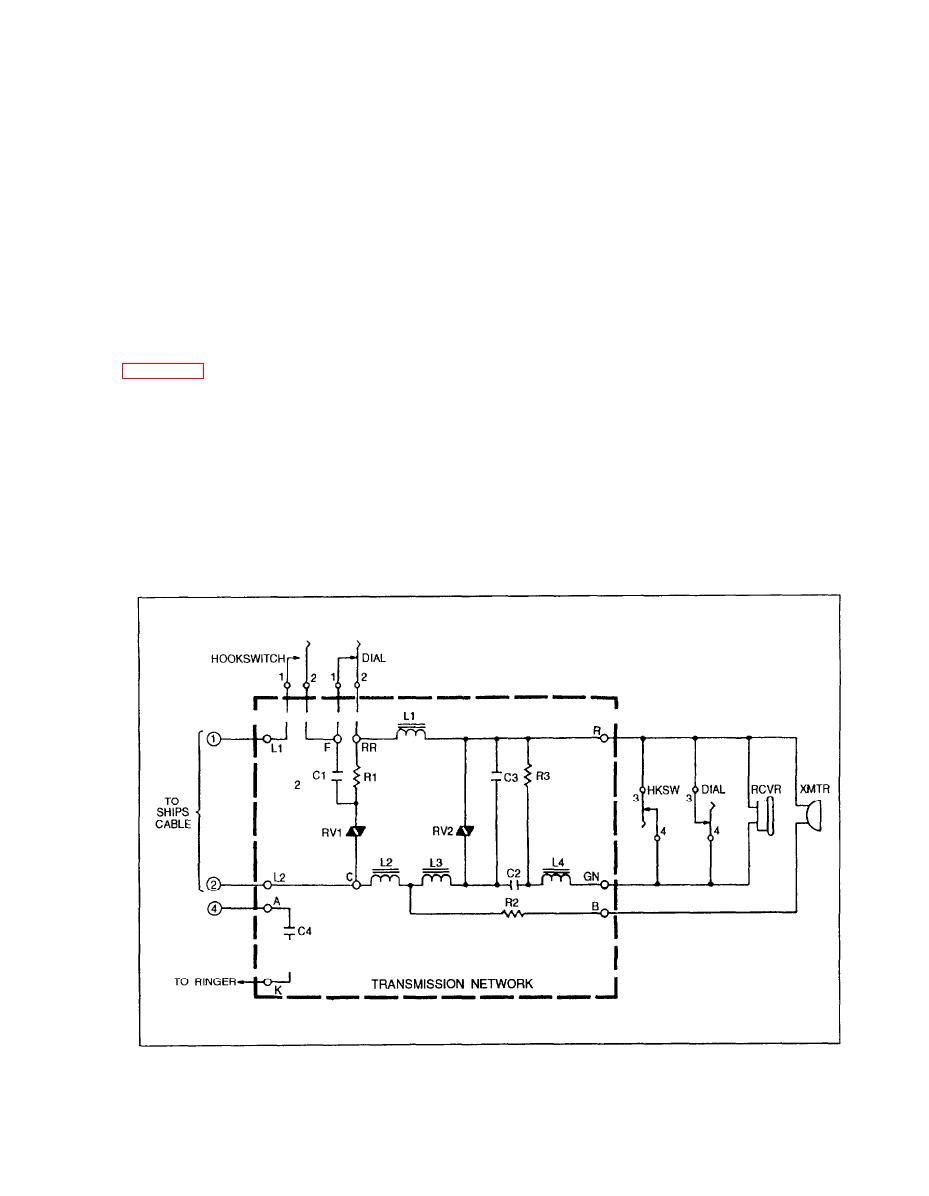 normally closed dial (impulse spring) contacts 1 and
SLIDE ASSEMBLY RELEASE CON-
2 and dc paths 1, 2, and 3.
TROL.-- The slide assembly release control is a
mechanical control that consists of a button that must
Dc path 1 is through resistor R1 and varistor RV1.
be depressed to unlock the handset retainer slide.
Resistor R1 limits the current through varistor RV1 to
When the handset retainer slide is unlocked, the
protect it from high line-voltage surges. Varistor RV1,
handset can be removed from the handset holder.
with varistor RV2, acts as an automatic gain control
to maintain a constant input and output level over the
TRANSMISSION NETWORK.-- The trans-
range of loop resistance encountered when used with
mission network is the control circuit for the telephone
any specific automatic dial telephone switchboard.
set. The transmitter output and all inputs to the
Dc path 2 is through inductor L1, the transmitter,
receiver are extended to and from the associated
resistor R2, and inductor L2. This path prepares the
automatic dial telephone switchboard under the
transmitter for audio excitation. Inductors L1 and L2
control of this circuit. This circuit also produces and
balance the line for varying levels of outgoing and
controls receiver sidetone (transmitter sounds
incoming audio signals. Resistor R2 limits the current
reproduced in the receiver of the same handset).
through the transmitter to protect it from high
line-voltage surges.
the transmission network circuit. The handset
Dc path 3 is through inductor L1, varistor RV2,
transmitter and receiver, the hookswitch contacts, and
and inductors L3 and L2. This is a balancing and gain
the dial contacts are also shown to simplify the
control path, with varistor RV2 acting with varistor
description of the circuit.
RV1 as described in path 1. Inductors L1 and L2
When the handset is removed from the handset
function as described in path 2. Inductor L3 aids in
balancing the circuit and, by mutual inductance,
holder, hookswitch contacts 1 and 2 close the dc loop
couples audio signals from the transmitter circuit to
between terminal 1 (L1) and terminal 2 (L2) by
6-4
|
|
Privacy Statement - Press Release - Copyright Information. - Contact Us |
