 |
|||
|
Page Title:
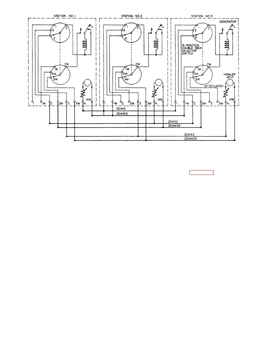
Figure 5-23.--Sound-powered magneto call circuit 2EM. |
|
||
| ||||||||||
|
|
 CIRCUIT MJ - MULTIPLE-TALKING AND
avoid the need of setting the station selector switch to
SELECTIVE RINGING CIRCUIT
the ANSWER position, which is required to use the local
call signal station handset. Figure 5-24 is an elementary
wiring diagram of an MJ circuit.
Circuit MJ provides a means of communication
with more than one conversation on the circuit
CALL AND SIGNAL CIRCUITS
simultaneously, as well as providing selective ringing at
MAINTENANCE
each station. In addition, the sound-powered telephone
and ringing circuits are combined to provide one
common talking circuit between all stations. Up to eight
You should accomplish preventive maintenance of
separate conversations are possible at one time. The
call and signal circuits according to the applicable
circuit may be used with any particular sound-powered
MRCs. Corrective maintenance will usually consist of
circuit where its capabilities would be advantageous.
isolating shorts, grounds, and opens in the circuits and
repairing or replacing the audible and visual signal
IC/D call signal stations are used with circuit MJ.
devices used with the circuits.
The internal wiring of each call signal station is revised
and a relay and diode assembly is mounted on the
selector switch of each call signal station. When the
SOUND-POWERED TELEPHONE
relay is de-energized, its contacts complete the circuit to
SYSTEM AN/WTC-2(V)
the local handsets at all call signal stations on the circuit.
When a caller cranks the hand-operated magneto
The AN/WTC-2(V) sound-powered telephone
generator at the calling station, it energizes the coil of
system is installed on some naval ships. This system
the relay at the called station. The contacts of the relay
replaces the existing EM and MJ call and signal circuits.
then close to complete the circuit to the howler at the
The system is designed for interior shipboard use and,
called station. At some call signal stations on the circuit,
along with the sound-powered telephone circuits
extension handsets are provided for convenience in
d i s c u s s e d earlier, provides two-way voice
answering incoming calls. The extension handsets are
communication between shipboard terminal stations.
connected to the "home station" circuit MJ wires to
You can signal and talk on the same cable. The system
|
|
Privacy Statement - Press Release - Copyright Information. - Contact Us |
