 |
|||
|
Page Title:
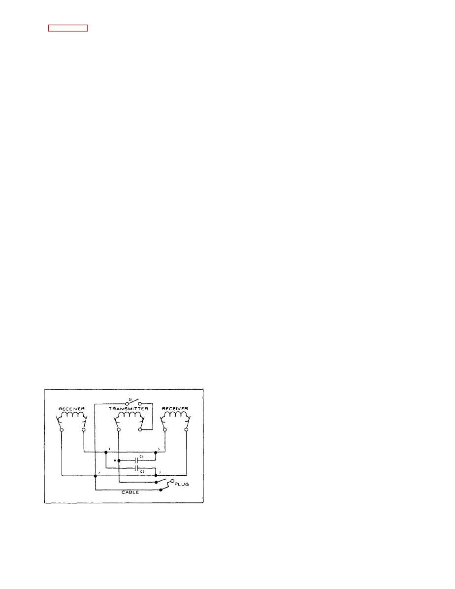
Figure 5-11.--Simplified sound-powered telephone headset-chestset schematic. |
|
||
| ||||||||||
|
|
 noise-attenuating shells consisting of plastic caps lined
with sound-absorbing material.
sound-powered telephone headset-chestset. Closing the
press-to-talk switch, S1, connects the sound-powered
SOUND-POWERED UNITS.-- The sound-
transmitter unit across the line. The receiver units are
powered transmitter and receiver units used in
permanently connected across the line when the set is
sound-powered telephone headset-chestsets are not
plugged in.
interchangeable. The units differ physically; however,
the principle of operation is the same for both.
Capacitor C1 is in the circuit to prevent the flow of
direct current through the receiver units when the set is
Sound-powered telephone headset-chestset
used on the output side of a sound-powered telephone
receiver units will transmit as well as receive. In the
amplifier. When the set is used on the output side of the
event the transmitter becomes defective, and the set
amplifier, a small dc voltage is placed across the set to
cannot be repaired at once, communication can still be
form an amplifier squelching circuit to avoid acoustical
maintained. Remove either one of the receiving units
feedback when the local set is transmitting. When the
from the headband and use it as a transmitter. Since the
press-to-talk switch, S1, is depressed, direct current
receivers are connected in parallel, either one can be
flows through the transmitter unit, causing a relay in the
used as the transmitter.
amplifier to operate and activate the squelching circuit.
HANDLING HEADSET-CHESTSETS.--
Sound-powered telephone headset-chestsets should be
Capacitor C2 provides for power-factor correction
handled with care so they will be working properly in
and improves the acoustical quality of the set.
the event of an emergency. When not in use they should
The H-200/U can also be modified to meet security
be correctly made up and stowed in their proper place.
requirements for use in the ship's communication center.
The sets are made as waterproof as possible, but
The headset-chestset cord must contain not less than two
they should not be exposed unnecessarily to the weather.
conductors in a single shield.
The cords should not be dragged over sharp edges,
pulled too hard, or allowed to kink. When unplugging
There are two other types of headset-chestsets used
the cord from a jack, always pull on the body of the plug
with the sound-powered telephone system. They are the
and never on the cord. If it becomes necessary to remove
H-201/U and the H-202/U.
the set from the talker's head, hang the set by the head-
The H-201/U is designed for use by plotters and
band and neck strap, and never by the connecting wires.
console operators. This set features a transmitter
DONNING HEADSET-CHESTSETS.-- When
suspended from the headband on an adjustable boom.
donning the headset-chestset, you should use the
The normally open, spring-loaded, press-to-talk switch,
following procedure:
S1, is in a junction box clipped to the talker's belt.
1. Remove the set from the stowage hook or
The H-202/U is a specially designed set for use in
stowage box.
high noise level areas. The receiver units are housed in
2. Hold the set and coiled cord in one hand.
3. Unhook the neck strap and unwind the coiled
cord. Do not allow the set to dangle by its connecting
wires; this could cause open leads.
4. Put the neck strap around the neck and secure it
to the chestplate.
5. Put on the receivers and adjust the ear cushions
for maximum comfort and exclusion of noise.
6. Straighten out any kinks in the connecting wires.
7. Test the headset for satisfactory operation by
blowing into the transmitter with S1 depressed. A
hissing noise should be heard in both receivers.
8. Remove the jack cover and connect the plug to
headset-chestset schematic.
the jack.
5-13
|
|
Privacy Statement - Press Release - Copyright Information. - Contact Us |
