 |
|||
|
Page Title:
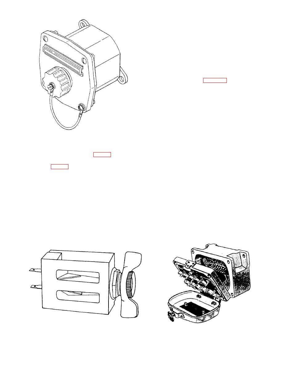
Figure 5-2.--Single-gang sound-powered telephone jackbox. |
|
||
| ||||||||||
|
|
 Most large combatant ships have several sound-
powered telephone switchboards installed in different
centrally located and protected control stations. Each
switchboard facilitates and controls several
sound-powered telephone circuits.
Switchbox Circuit
A s w i t c h b o x c i r c u i t originates from a
sound-powered switchbox. Figure 5-4 is an illustration
of a type A-17A sound-powered telephone switchbox.
Each telephone station jackbox in the circuit connects
to a line cutout switch in the switchbox. The line cutout
switch either connects or disconnects an individual
telephone station jackbox from its circuit. There are also
tie lines and tie switches installed to allow paralleling
with circuits in other switchboxes or switchboards.
Switchboxes contain either 10 or 20 switches and
function primarily as small action cutout (ACO)
switchboards. Switchboxes are normally located at the
section from the sound-powered telephone switchboard.
station having operational control over the circuit or
Each telephone station jackbox (fig. 5-2) in the circuit
circuits concerned. Usually, there is only one circuit in
is connected to a switchjack on the switchboard. The
a switchbox.
switchjack (fig. 5-3) is a combination line cutout switch
and telephone jack. The line cutout switch portion of the
switchjack either connects or disconnects a telephone
String Circuit
station jackbox from its circuit. The jack portion of the
switchjack either parallels the telephone station
A string circuit consists of a series of telephone
associated with a particular switchjack to another circuit
station jackboxes connected in parallel to a common
or parallels two entire circuits. This method of
line. There are no line cutout switches provided for
paralleling is accomplished by a patching cord. A
cutting out individual stations. However, some string
patching cord is a short length of portable cord having
circuits are connected to communication consoles,
a jackplug at each end. The lines and tie switches are also
selector switches, and plotter transfer switchboards.
installed to allow paralleling with circuits on other
These will be discussed later in this chapter.
switchboards or switchboxes.
Figure 5-3.--A switchjack.
|
|
Privacy Statement - Press Release - Copyright Information. - Contact Us |