 |
|||
|
Page Title:
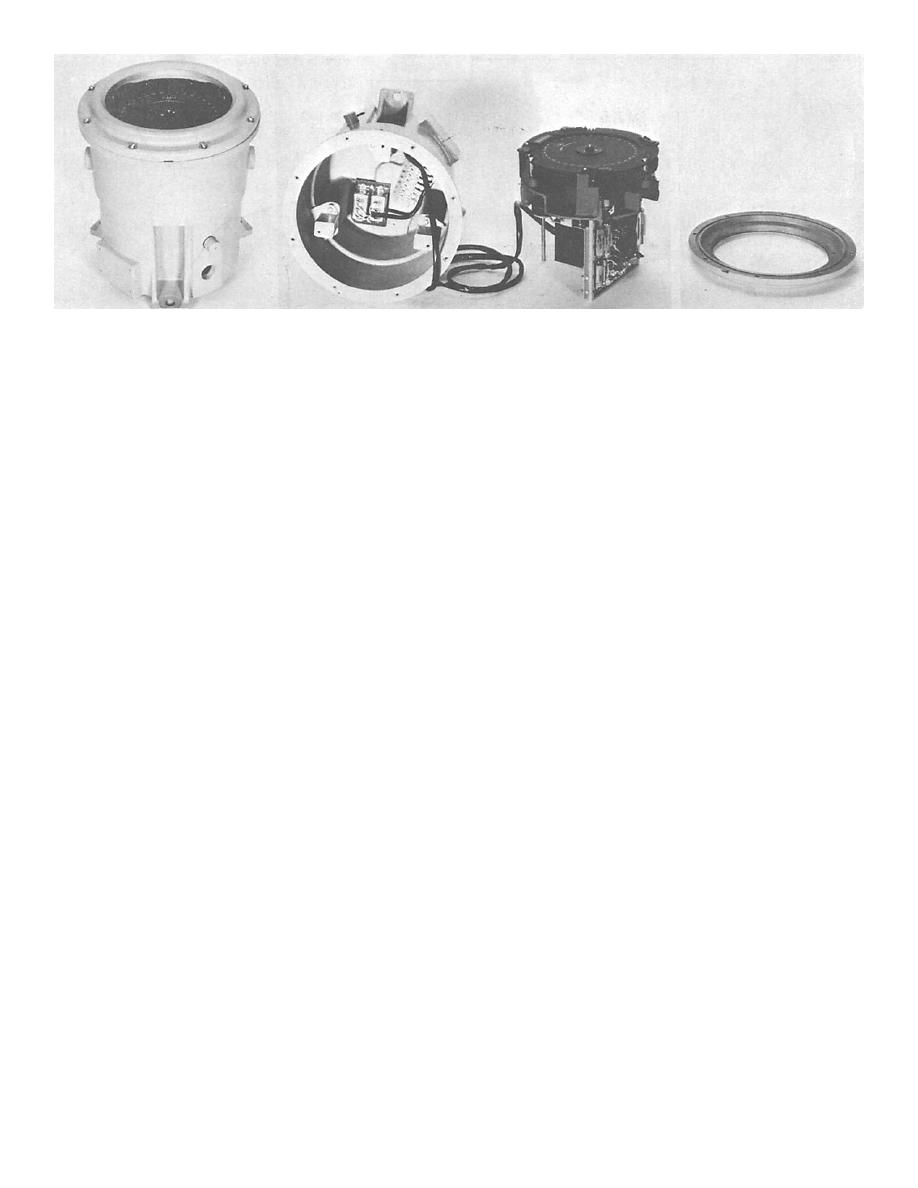
Figure 4-52.--Type E ship's course indicator |
|
||
| ||||||||||
|
|
 40.129
the 180 point, the servo would drive away from this
The use of the mixing network eliminates every
false null; but, because the 36X voltage has control, it
false null except the one at the 180 point of the
drives the servo toward this 180 point. The 36X
indicator dial. This null is eliminated by adding a 2.5-
error voltage (negative between 175 and 180) tends
volt, 400-Hz, antistickoff voltage in series with the 1X
to drive the servo to an increased angle (180). The
synchro rotor voltage, and shifting the phase of the
36X voltage is positive between 180 and 185, and
1X synchro voltage by 2.5 to bring the indicator null
tends to drive the servo to a decreased angle (180),
back to a true reading. This procedure converts the
the same point. In other words, if this condition were
180 point to an unstable (or recentering) null. If the
tolerated, the servo would lock in at a false null.
coarse (1X) and fine (36X) control transformers were
installed (adjusted to the same electrical zero as the
To remove this condition (false null), an
electrical zero position of the compass transmitters),
antistickoff voltage of 2.5 volts is obtained from a
there would be a position of the coarse control
transformer in the amplifier unit and applied to the
transformer shaft 180 out of correspondence with
coarse error voltage. This voltage is applied either in
the compass transmitter, at which the rotor volt ages
phase or 180 out of phase with the 1X error voltage
of both the coarse and fine control transformers
and is sufficient to shift the IX error signal null
would again both equal zero. Thus, the coarse
points 2.5. The resultant voltage does not pass
synchro system provides two null points in a complete
through the zero reference position of the 36XCT
cycle. Regarding the coarse control transformer
voltage. To restore the resultant voltage to the zero
(1XCT), its null at the 180 point is an unstable null,
reference position, the 1XCT stator is shifted 2.5 in
because if the shaft were on either side of that point,
its housing. Thus, the resultant 1X error voltage is
by an infinitesimal angle, the servo would drive
shifted a total of 5, which corresponds to 180
toward the correct null, 180 away. The fine synchro
rotation (36 x 1X) of the 36X synchro.
has 72 null positions or 36 times as many as the
coarse synchro system. If only the fine control
With antistickoff bias, the false null at the 180
transformer (36XCT) were connected in the system,
point cannot be attained by virtue of the 36X or 1X
there would be 36 positions of the transmitter shaft
error signal on either side of this point, both being of
that would produce a stable null error voltage. Only
such polarity as to drive in the same direction to the
one of these 36 positions is desired, that position
real null at zero degrees. The 36X error signal drives
being the point where the 1XCT also provides a stable
2.5 toward the correct null and then the mixing
null.
network switching to the 1X error signal, which
drives to 2.5 of the zero degree null position.
The mixing network switches the fine error signal
into the servoamplifier when the error is small
As the 2.5 point is reached, the mixing
(output of the coarse synchro is small) and introduces
circuit automatically shifts the amplifier input
the coarse error signal to the amplifier when the
signal from the 1X synchro to the 36X synchro.
error is large (output of the coarse synchro is large).
This signal, with amplifier output and motor
The coarse error signal can be small enough at the
torque reacting accordingly, is reduced as the
180 point to result in the tine error signal being fed
servo approaches null. The final null position is
into the servo, through the action of the mixing
reached at the point of minimum 36X synchro
network. If only the 1X error voltage were applied at
|
|
Privacy Statement - Press Release - Copyright Information. - Contact Us |