 |
|||
|
|
|||
| ||||||||||
|
|
 controlled by the DISPLAY potentiometer are shown in
Illumination Control
Two circuits control the level of illumination of the
control-indicator's panel lighting and indicators. These
Power Supplies
circuits are illustrated in block diagrams in figures 4-49
and 4-50.
There are two power supplies to the AN/WSN-2
gyrocompass. These are the backup power supply and
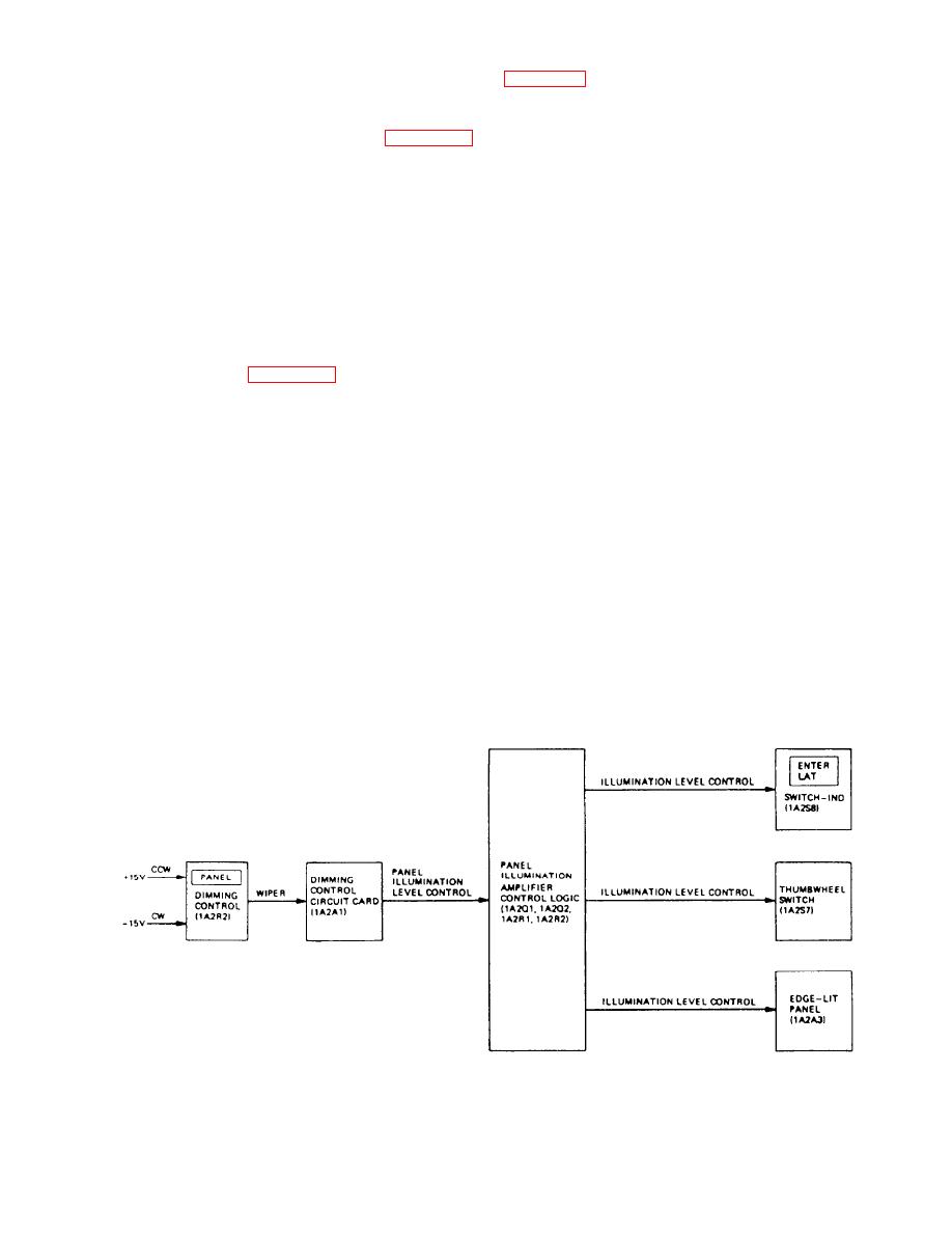
PANEL LIGHTING.-- The control indicator
the normal power supply.
panel lighting is controlled by a potentiometer marked
PANEL. The PANEL potentiometer is excited by 15
BACKUP POWER.-- The backup power supply
volts dc. The potentiometer adjusts a biasing level
consists of the inverter and the inverter module, located
applied to the illumination sensing circuit in the
in the synchro signal amplifier, for backup during loss
dimming control circuit card. The output of the sensing
of single-phase power, and the battery set and relays
circuit drives the dimming control amplifier. The output
located on the transformer-rectifier assembly, for
of the dimming control amplifier is an aboveground
backup during loss of 3-phase power.
variable voltage determined by the position of the
NORMAL POWER.-- The normal power supply
PANEL potentiometer. Figure 4-49 identifies the lights
consists of the control monitor, battery charger, 5-volt
controlled by the PANEL potentiometer.
regulator, 13-volt regulator, DC/DC module, and
STATUS INDICATOR AND DISPLAY
transformer rectifier. These are all located in the control
LIGHTING.-- The control indicator's status indicators
power supply. Three-phase, 115-volt ac ship's power is
and the digital display are controlled by the DISPLAY
routed through an EMI filter and power circuit breaker
potentiometer. The potentiometer provides a triggering
to the transformer rectifier for normal power. The
level input (0 volts to +5 volts) to a controlled-width
transformer rectifier converts the 115 volts ac to 35 volts
blanking pulse circuit, located on the dimming control
dc and unregulated 28 volts dc. The 35 volts dc goes to
circuit card. The blanking pulse is applied to the
the battery charger and the unregulated 28 volts dc is
indicator enabling logic, also on the dimming control
sent to the 5-volt and 13-volt regulators.
circuit card. When the input to any indicator, controlled
The battery charger receives high- and low-voltage
by the DISPLAY potentiometer, is determined to be
sensing signals and a temperature-sensing signal from
correct by the display logic, the indicator is energized.
the battery set. The battery charger uses the
The period of the blanking pulse, established by the
temperature-sensing signal to regulate the 35 volts dc to
DISPLAY potentiometer, determines the illumination
provide a charging voltage to the battery set. The
level. Indicators on the control indicator that are
4-54
|
|
Privacy Statement - Press Release - Copyright Information. - Contact Us |
