 |
|||
|
Page Title:
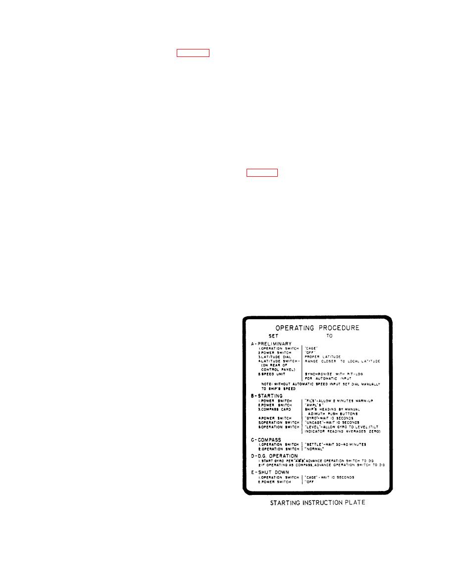
Figure 4-16.--0perating procedures for the Sperry Mk 23 Mod 0 gyrocompass. |
|
||
| ||||||||||
|
|
 B-51 or B-52 alarm panel is used in place of the
MK 23 MOD 0 GYROCOMPASS SYSTEM
annunciator.
The Mk 23 Mod 0 gyrocompass system (fig. 4-15)
consists of the master unit, control cabinet, speed unit,
Alarm Bell
alarm control unit, a compass failure annunciator, and
an alarm belt.
The alarm bell is used with the annunciator to
provide an audible indication of problems within the
Master Unit
gyrocompass system.
The master unit consists of a shock-mounted,
OPERATING THE MK 23 MOD 0
oil-filled binnacle and the gyrocompass element. The
GYROCOMPASS
master unit is designed for deck mounting and weighs
approximately 100 pounds. The compass element is the
Instructions for starting and stopping (securing) the
principle unit of the compass system and is gimballed
compass under normal conditions are on an instruction
in the binnacle to allow 45 of freedom about the pitch
plate (fig. 4-16). This plate is located on the front of the
and roll axes. Drain plugs are located in the lower bowl
control cabinet. There are two modes of operation,
for draining the oil.
normal and directional gyro (DG). The normal mode of
operation is used for latitudes up to 75. The DG mode
Control Cabinet
of operation is used for latitudes above 75. Normally,
the compass should be started at least 2 hours before it
The control cabinet contains all the equipment
is needed for service. For additional information on
required for operating and indicating the condition of
starting the compass, refer to the manufacturer's
the master compass except the visual alarm indicator
technical manual.
and the alarm bell. The control cabinet houses the
If it becomes necessary to stop the compass in a
control panel, control amplifier, follow-up amplifier,
heavy sea for any reason other than failure of the
and power supply.
follow-up system, the following procedure should be
used:
Speed Unit
The speed unit contains the necessary components
to produce an electrical signal proportional to ship's
speed. Speed information is received from the ship's
underwater log equipment or is set in manually by the
ship's dummy log system. The speed range of the unit
is 0 to 40 knots.
Alarm Control Unit
The alarm control unit contains the necessary relays
and components to actuate the lamp on the visual alarm
indicator or the bell alarm when certain portions of the
system become inoperative.
Compass Failure Annunciator
The compass failure annunciator is a visual alarm
indicator. It provides a visual indication of problems
within the gyrocompass system. Under normal
conditions, the lamp on the indicator is lighted
continuously. When a failure occurs within the system,
the lamp flashes or goes out. A test push button is
Mod 0 gyrocompass.
provided on the annunciator. In some installations a type
|
|
Privacy Statement - Press Release - Copyright Information. - Contact Us |
