 |
|||
|
Page Title:
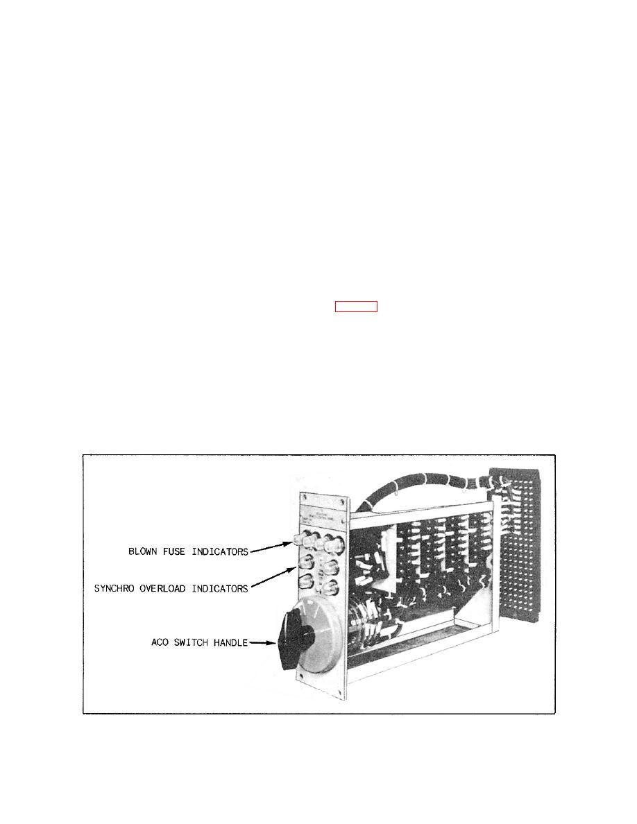
Figure 3-5.--ACO drawout switch unit. |
|
||
| ||||||||||
|
|
 Panel 3 is supplied with 250 volts dc from one of
the fleet, the ABT is located separate from the
two 450-volt, 3-phase, 60-Hz motor generators. Two
switchboard itself.
stop-start switches, power available indicator lights
for each source, and a voltmeter are located on panel
The normal power supply is from the forward
3. The motor generators obtain their power from the
ship's service distribution switchboard. The
450-volt, 60-Hz, 3-phase bus.
alternate power supply comes from the after
ship's service distribution switchboard. The
emergency power supply comes from the forward
PANEL 4.-- The 450-volt, 400-Hz, 3-phase power
emergency distribution switchboard. The bus
for panel 4 is received from a motor generator or a
may also be energized by a casualty power
static power supply. The 120-volt, 400-Hz, 3-phase
terminal installed on the board, which, in turn,
power is received from a bank of transformers. A
receives its power via portable cable from a
remotely located riser nearby.
also installed on panel 4 for monitoring by watch
standers and maintenance personnel.
PANEL 2.-- The 120-volt, 3-phase, 60-Hz bus
located in panel 2 receives its power from panel
ACO Section
1 via a bank of three 450/120-volt, 60-Hz, single-
phase transformers located in panel 2. This
The ACO section (panels 5 and 6) permits isolation
panel disseminates both 120-volt, single-phase,
of damaged portions of certain IC systems and, in
60-Hz, and 120-volt, 3-phase, 60-Hz power to
addition, allows transfer control of certain systems
various IC and FC systems as required. A
from one station to another. Drawout switch units
voltmeter, an ammeter, and a megohmmeter are
installed on the front of panel 2 for monitoring
associated JR switch, fuse holders, synchro overload
by watch standers and maintenance personnel.
transformers, and overload indicators.
PANEL 3.-- Panel 3 is supplied with 120
The switches found on these panels are for the
volts dc from the 450-volt supply of panel 1 via
repeater and control circuits of the gyrocompass,
two remotely located rectifiers. A switch on the
wind indicating, propeller revolution, propeller order,
front of panel 3 allows the operator to select
engine order, and underwater log systems.
either of the two rectifiers. Indicator lights on
the panel indicate which of the two rectifiers is
Through the proper manipulation of switches,
in operation.
either the main or the auxiliary gyrocompass may be
|
|
Privacy Statement - Press Release - Copyright Information. - Contact Us |
