 |
|||
|
Page Title:
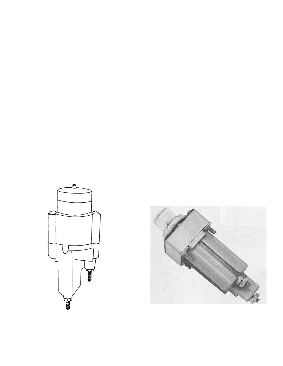
Figure 2-31.--Type EL-1 fuse holder. |
|
||
| ||||||||||
|
|
 holders, separate indicator light circuits are mounted
therefore be used to fuse both sides of the line, or, in
on a panel and connected in parallel with separately
conjunction with a type FHL11G, will fuse a 3-phase
mounted fuses and fuse clips. In some cases an alarm
line. Type FHL12G will accommodate 1 1/2- by 13/32-
circuit in the form of a bell or buzzer takes the place
inch fuses. When these fuse holders are mounted in a
of the indicator light.
dripproof enclosure, they maintain the dripproof
integrity. They also possess the ruggedness and the
vibration and high-impact shock resistance necessary
Troubleshooting Fuse Circuits
for shipboard use.
An electrical system may consist of a
The extensive use of low-voltage power supplies
comparatively small number of circuits or, in the
has required the use of incandescent lamps in place of
larger systems, the installation may be equal to that
neon glow lamps in some indicator light circuits. A
of a fair-sized city.
modification of the FHL10U fuse holder provides a
third terminal connected to a 28-volt incandescent
Regardless of the size of the installation, an
lamp in the cap. By insertion of a suitable resistor
electrical system consists of a source of power
between the load terminal and the added terminal,
(generators or batteries) and a means of delivering
the lamp will be energized by a sufficient voltage to
this power from the source to the various loads
become visible when the fuse has blown. In some low-
(lights, motors, and other electrical equipments).
voltage fuse holders the resistor and lamp are
included within the clear plastic cap. Low-voltage
From the main power supply the total electrical
fuse holders should not be used in sensitive, low-
load is divided into several feeder circuits, and each
current equipment. Where an overload condition
feeder circuit is further divided into several branch
occurs and the fuse blows, the low-resistance
circuits. Each final branch circuit is fused to safely
indicator circuit may pass sufficient current to
carry only its own load, while each feeder is safely
damage the equipment.
fused to carry the total current of its several
branches. This reduces the possibility of one circuit
Due to the design of certain fuses and in cases
failure interrupting the power for the entire system.
where space does not permit indicator-type fuse
The feeder distribution boxes and the branch
distribution boxes contain fuses to protect the various
circuits.
The distribution wiring diagram showing the
connections that might be used in a lighting system is
140.13
|
|
Privacy Statement - Press Release - Copyright Information. - Contact Us |
