 |
|||
|
|
|||
| ||||||||||
|
|
 rates. A heater is mounted around, or close to, the
of the contacts can be observed and the relays are
element, with the contacts mounted on the element
easily available for maintenance. Relays B, C, and F
itself. As the heat causes the element to bend (because
are semisealed relays. The covers provide protection
of the different thermal expansion rates), the contacts
from dust, moisture, and other foreign material, but
close to operate a relay. The delay time of the
can be removed for maintenance. Relays A and D are
bimetallic strips is usually from 1/2 to 1 1/2 minutes
examples of hermetically sealed relays. These relays
are protected from temperature or humidity changes
and is varied by using metals with different expansion
rates or by increasing or decreasing the distance
as well as dust and other foreign material. The covers
between the fixed and moving contacts.
cannot be removed, thus making the relay tamper-
proof.
One common form of time delay relay uses a lag
coil, which is usually a large copper slug located at
Clapper Relay
one end of the winding or a tubular sleeve located
between the winding and the core. The lag coil (slug)
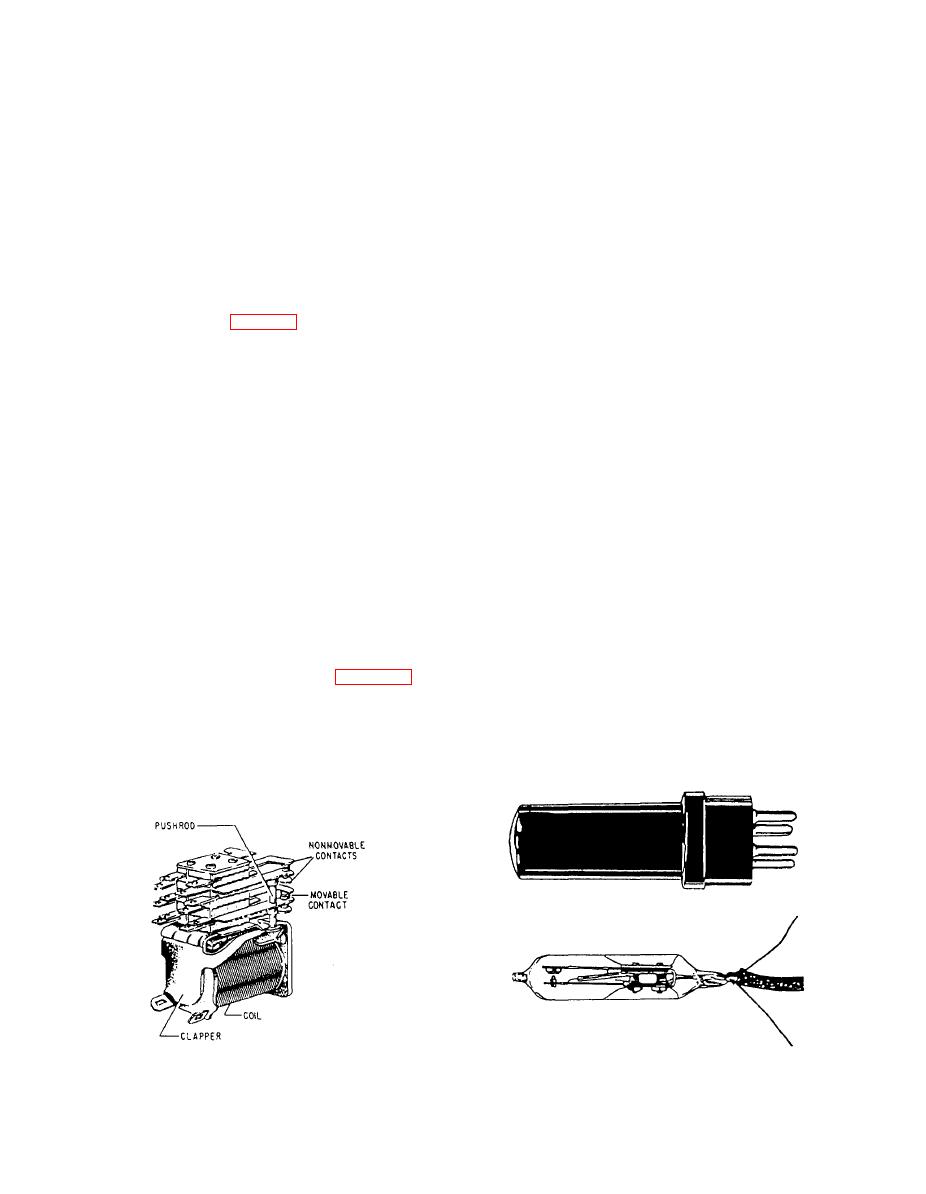
The clapper relay (fig. 2-22) has multiple sets of
acts as a short-circuited secondary for the relay coil.
contacts. As the circuit is energized, the clapper is
The counter magnetomotive force (mmf), due to the
pulled to the magnetic coil. Pulling the arm of the
current induced in the coil by the changing coil
clapper forces the movable contact upward to move
current, delays the flux buildup or decay in the air gap
the pushrod and the upper movable contact. This
and hence the closing or opening of the armature. A
action could be repeated for as many sets of contacts
short slug near the armature end of the core has
as required. Thus, it is possible to control many
relatively more effect on the operating time, and one
different circuits simultaneously. To the maintenance
at the heel end has more effect on the release time.
person, this type of relay can be a source of trouble.
The motion of the clapper arm does not necessarily
Latch-In Relay
assure the tandem movement of all the movable
contacts. If the pushrod was broken, the clapper arm
Another type of relay is the latch-in relay. This
would push the lower movable contact upward but
relay is designed to lock the contacts in the
would not move the upper moveable contact, thereby
de-energized position until the relay is either
not completing the circuit.
manually or electrically reset. Two windings are used:
the trip coil and the reset coil. When the trip coil is
Thermal Time Delay Relay
energized, it acts on a spring-loaded armature. The
movable contacts of the relay are mounted on this
A thermal time delay relay (fig. 2-23) is
armature. After the contacts open they are held in the
constructed to produce a delayed action when
open position by a mechanical latch. The mechanical
energized. Its operation depends on a thermal action,
latch is unlatched when the reset coil is energized,
such as that of a bimetallic element being heated. The
thus allowing the relay's contact to close again.
element is made by welding together two strips of
different metals having different thermal expansion
2-15
|
|
Privacy Statement - Press Release - Copyright Information. - Contact Us |
