 |
|||
|
Page Title:
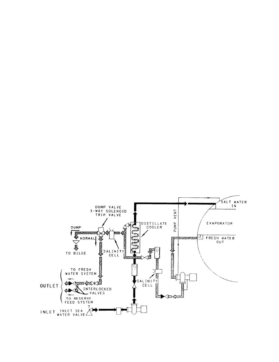
Figure 10-39.--Ships' water system diagram. |
|
||
| ||||||||||
|
|
 speed and distance information to various equipment
VALVE POSITION INDICATOR SYSTEMS
and remote indicators throughout the ship.
Valve position indicator systems (circuit VS) pro-
The main internal components of the indicator-
vide personnel at remote stations of the positions (open
transmitter are the speed servo, the integrator, and the
or closed) of certain valves.
distance servo. The main external components of the
Sensitive switches, mounted on the valve housing
indicator-transmitter are a distance motor, a speed dial,
and actuated by the valve, energize the indicators. On
a distance counter, an electronic trim pot assembly, and
most installations, you will find two switches. One
a dummy signal unit used for calibration.
switch indicates that the valve is open and the other
The ac signal voltage produced by the rodmeter is
indicates that the valve is closed. They normally have a
fed to the speed servo. The speed servo drives the
make contact arrangement. There are usually two lamps
synchro output transmitters, the dual-pointer dial, and
in each indicator; one lamp for the open position of a
the integrator. The integrator converts the speed input
valve and the other for the closed position. The remote
to a distance-traveled output, which drives a synchro
indicators may be found singly, but they are normally
output transmitter and a six-drum counter to display
grouped into valve position indicator boards of from 5
distance traveled.
to 15 indicators to indicate the positions of valves
located in the same engineering space.
Remote Control Unit
SALINITY INDICATOR SYSTEM
The remote control unit, or dummy log as it is
commonly called, is used in place of the rodmeter
The salinity indicator system, described in this
when the ship is operating in shallow water, where
chapter, is a representative system. When working on
lowering the rodmeter is impractical. The unit is
the salinity system on your ship, you should consult the
normally located in the main propulsion control
technical manual pertaining to your equipment for spe-
station. The unit has a spring-loaded, center-off,
cific settings.
increase-decrease switch and is operated by the
The salinity indicator system (circuit SB) measures
throttleman. The shaft rpm is used to determine
the electrolytic impurities present in fresh water in
approximate ship's speed.
equivalent parts per million (epm) or parts per million
|
|
Privacy Statement - Press Release - Copyright Information. - Contact Us |
