 |
|||
|
Page Title:
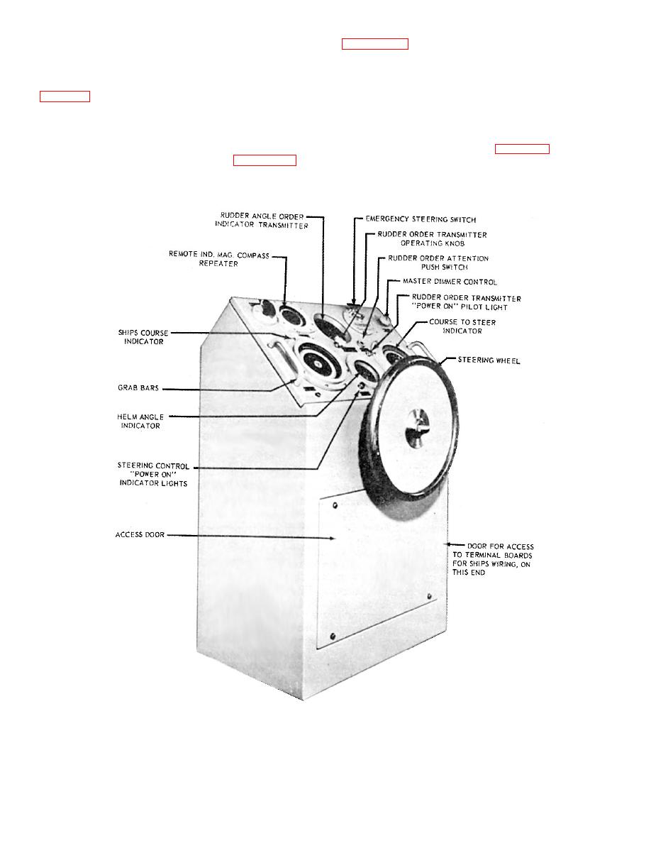
Figure 10-8.--Steering control console. |
|
||
| ||||||||||
|
|
 .indicator-transmitter to energize the appropriate bell
order system, showing the various units and their
on the ship's control console.
locations for circuit MB. The associated remote
indicator stations are also included in the diagram.
Each fireroom has a double engine order indicator
requirements.
STEERING CONTROL
CONSOLE
Engine order indicators are also located in other
stations on the ship, such as the combat information
The steering control console (fig. 10-8) incorporates,
center (CIC) and the navigation bridge. Figure 10-6 is
in a single unit, the equipment required to navigate the
an illustration of a single engine order indicator.
ship from the pilothouse and to transmit
7.133
|
|
Privacy Statement - Press Release - Copyright Information. - Contact Us |
