 |
|||
|
Page Title:
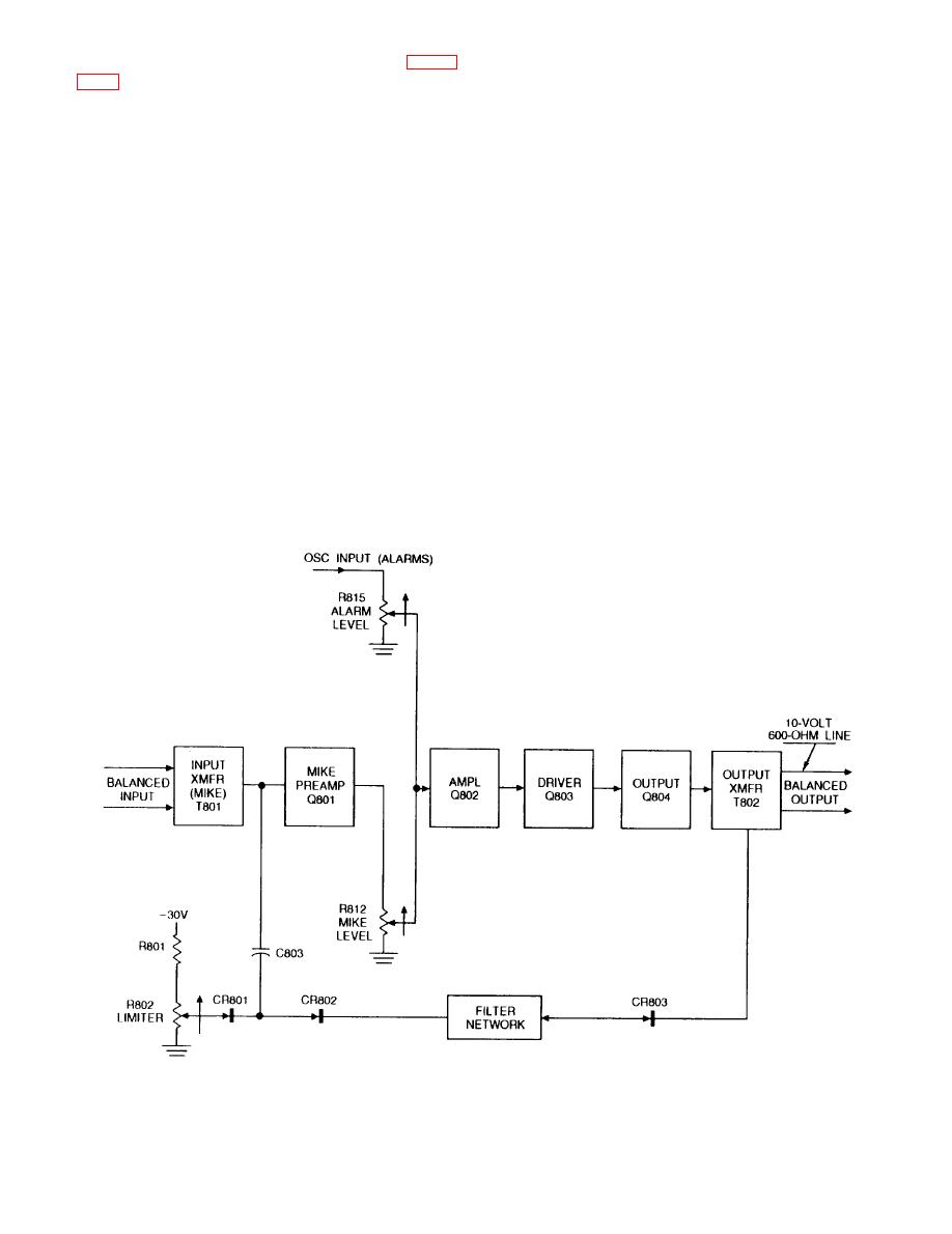
Figure 7-10.--Block diagram of a preamplifier. |
|
||
| ||||||||||
|
|
 their associated power amplifier to full output. Figure
the microphone and oscillator amplifier of the
channel selected for use on circuit 1MC. The output
from the power rack is distributed to all circuit 1MC
Power Supply Modules
loudspeaker groups. Alarm signals are not transmitted
over the circuit 6MC loudspeakers. The alarm modules
Two power supply modules are located in the
in the order of their priorty are (1) collision, (2)
control rack. Each power supply is a regulated transistor
chemical, (3) general, (4) unassigned A, and (5) flight
unit that supplies -10 volt dc and -30 volt dc operating
crash.
voltages to the alarm modules and preamplifier
modules.
The order of priority is controlled automatically by
relays in the control rack. Any alarm takes priority over
Alarm Modules
voice announcements.
COLLISION ALARM.-- The collision alarm is a
Ten alarm modules are located in the control
transistorized oscillator circuit that generates a
rack, five for each oscillator group. Each alarm
signal composed of three 1000-Hz bursts. Each
module, when actuated by an alarm contact maker,
burst is 60 milliseconds duration. The first and
is capable of generating an audio-frequency alarm.
second burst is followed by an off time of 60
When an alarm signal is actuated, all microphone
control stations are automatically disconnected by
milliseconds. The third burst is followed by an off
time of 420 milliseconds. This cycle repeatedly
(alarm signal) is then connected to the alarm input of
continues as long as power is applied to the circuit.
7-11
|
|
Privacy Statement - Press Release - Copyright Information. - Contact Us |
