 |
|||
|
Page Title:
Figure 6-36.--Block diagram of linefinder operation. |
|
||
| ||||||||||
|
|
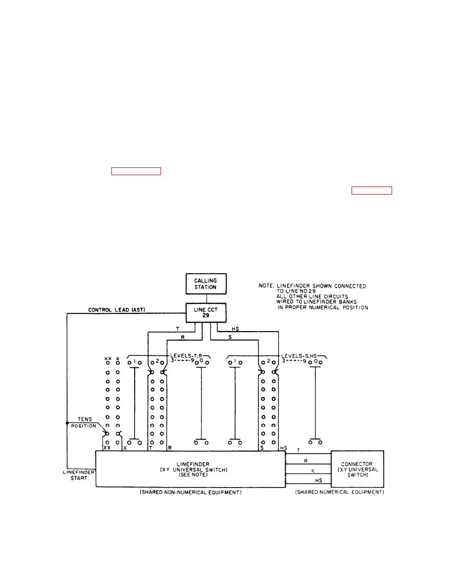 save space, switching equipment is shared. The main
linefinder start signal to the linefinder. This signal
pieces of equipment used in linefinding are the line
causes the XY switch to step automatically in the X
circuit, the linefinder, and the allotter.
direction, searching for the level in the wirebank
where the calling line is located. The XX-X bank and
LINE CIRCUIT.-- Since the shared equipment
wipers serve to indicate the tens level (level 4 would
must be available to all line stations on an equal basis,
be the tens level for line 45) of the calling line. When
there must be a method of indicating that a line station
the XY switch reaches this level, it stops and starts
requires switching equipment. The line circuit
moving into the wire bank in the Y direction. When
performs this task by sending a signal to the switching
the proper line is located, it stops again and
equipment when a station wishes to originate a call
establishes the necessary connections so that the
(lifts the receiver from the cradle to operate the hook
calling station may control the connector with the dial
switch). There is one line circuit associated with each
line station in the system, arranged so that on an
and complete the call. A dial tone then informs the
incoming call to the station, the shared switching
calling party that the line has been found. The
equipment is not connected to the station.
linefinder remains connected to the line during the
entire call and is released when the calling party hangs
up the handset.
basic principles of linefinding. For the sake of
simplicity, the allotter is not shown. When the calling
Only one linefinder is shown in figure 6-36. When
party operates the hook switch by removing the
other calls are made simultaneously from other
handset from the cradle, the line circuit sends a
stations, additional linefinders must be available. The
6-39
|
|
Privacy Statement - Press Release - Copyright Information. - Contact Us |
