 |
|||
|
Page Title:
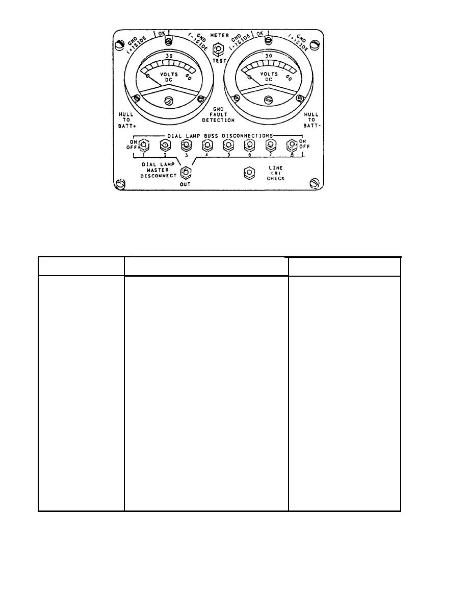
Table 6-5.--Ground Fault Detection Panel, Controls and Indicators |
|
||
| ||||||||||
|
|
 DESIGNATION
FUNCTION
POSITION/INDICATION
HULL TO BATT
Indicates voltage between system positive
0--60 volts dc.
+ Meter
supply bus and ship's hull.
HULL TO BATT
Indicates voltage between system negative
0--60 volts dc.
Meter
supply bus and ship's hull.
Disconnects ship's hull from circuit and
METER/TEST
Test (down)--ship's hull in
places meter directly across power supply.
Switch
circuit.
Meter (up)--ship's hull out
of circuit, meters are
across power supply.
DIAL LAMP
Disconnects lamp buses from the power
On (up)--lamp bus con-
nected.
BUS DISCON-
supply.
NECTS Switches
Off (down)--lamp bus dis-
connected.
Disconnects all lamp buses from phone
Up--lamp buses connected.
DIAL LAMP
MASTER DIS-
station dial lamps.
Out (down)--lamp buses
disconnected.
CONNECT Switch
Disconnects ATBT lead at oscillator board.
Up--ATBT lead discon-
LINE (R)
nected.
CHECK Switch
Down--ATBT lead con-
nected.
|
|
Privacy Statement - Press Release - Copyright Information. - Contact Us |
