 |
|||
|
Page Title:
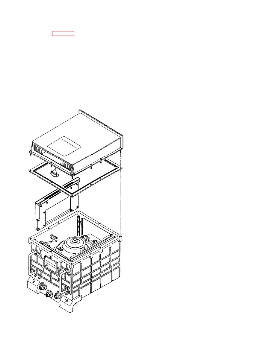
Figure 4-47.--Inertial measuring unit exploded view. |
|
||
| ||||||||||
|
|
 FUNCTIONAL DESCRIPTION
INERTIAL MEASURING UNIT
The primary function of the stabilized gyrocompass
The IMU (fig. 4-47) is installed in a special
set is to produce precision analog dual-speed roll, pitch,
precision IMU alignment rack located in the bottom of
and heading signals for use by the ship's equipment. The
the electrical equipment cabinet, behind an access cover.
outputs are available in all modes during normal
Access to the IMU is gained by removing the access
operation and battery backup. When operating on
cover. The IMU contains the gimbal assembly, the
inverter produced single-phase power, only vital
electronics necessary to maintain the gimbal assembly,
heading and its synchro reference are available.
and associated electronics necessary to interface with
For the stabilized gyrocompass to operate, it
the control, computing, and processing functions of the
requires certain electrical inputs from the ship. These
control power supply. The IMU also contains BITE
inputs are 115-volt ac, 400-Hz, single-phase synchro
circuitry and indicators and houses temperature
excitation; 115-volt ac, 400-Hz, 3-phase primary power;
controlling electronics.
underwater log data with reference voltage; and 24-volts
dc provided internally by the battery set and used during
the loss of 3-phase input power.
SIGNAL DEVELOPMENT
The roll, pitch, and heading (in some publications
referred to as azimuth) located in the IMU gimbal are
excited by 26 volts, 4.8 kHz when the gimbal is caged,
or by 26 volts, 400 Hz during normal operation. Both
resolver excitation levels are provided by the
servoamplifier. Each resolver has two outputs, which
represent the sine and cosine of the angular
displacement of its respective rotor shaft. These outputs
are sent back to the servoamplifier when the gimbal is
caged. When the gimbal is uncaged, during normal
operation, the outputs are sent to the resolver
preamplifier.
The roll and pitch sine and cosine signals from the
resolver preamplifier are amplified, buffered, and
converted to standard three-wire format by the synchro
signal amplifier. The data leaves the synchro signal
amplifier as S1, S2, and S3 synchro data.
The heading sine and cosine signals from the
resolver preamplifier are converted to true heading sine
and cosine signals in the 1X and 36X true heading
converters before being sent to the synchro signal
amplifier and the analog/digital (A/D) multiplexer. The
true heading sine and cosine data, like the roll and pitch
data, are amplified, buffered, and converted to standard
three-wire synchro data in the synchro signal amplifier.
True heading data is subsequently sent out as S1, S2,
and S3 synchro data.
The roll, pitch, and heading sine and cosine signals
from the resolver preamplifier and the true heading sine
and cosine signals from the true heading converter are
also sent to the A/D multiplexer. The A/D multiplexer
sends these analog signals to the A/D converter, where
|
|
Privacy Statement - Press Release - Copyright Information. - Contact Us |
