 |
|||
|
Page Title:
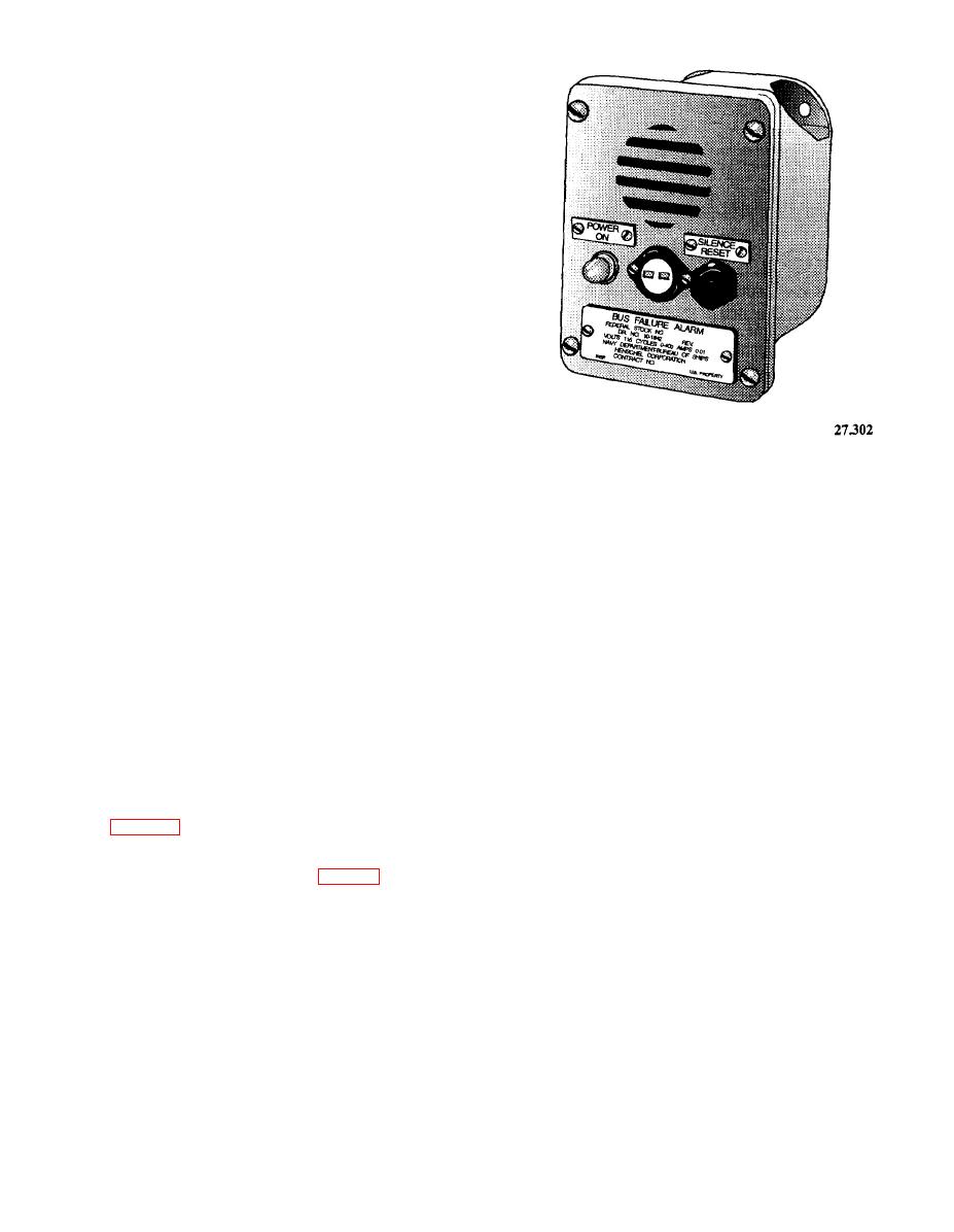
Figure 3-8.--Type IC/E1D1 electronic signal unit. |
|
||
| ||||||||||
|
|
 to the dropout range and relays 1V, 2V, and 3V drop
out. Contact 1Val opens, disconnecting relay SE.
After a time delay of 0.3 to 0.5 seconds, relay SE
opens, closing its SEb1 and SEb2 contacts and
energizing relay 4V from the emergency source.
When contact 4Val closes, it connects the emergency
source to coil TS of the transfer switch, which, in turn,
operates, transferring the load to the emergency
source.
After a short delay, contacts TSa4 and TSa5 open,
disconnecting coil TS from its operating circuit.
However, TS is now being held in the operated
condition mechanically. This completes the transfer to
the emergency supply.
Upon restoration of the normal power to the
selected range, the retransfer is begun by the
energizing of relays 1V, 2V, and 3V, which close,
energizing relay SE. Contacts SEb1 and SEb2 now
open, disconnecting relay 4V from the emergency
source. After the time delay, relay 4V opens, closing
its 4Vb1 contact and completing the normal supply
circuit to the transfer switch coil, TS, which again
The POWER ON light, a backlighted push button,
operates, transferring the load back to the normal
tests the audible signal of the unit. The SILENCE
supply.
RESET push button silences the alarm (the red flag
When you put the ABT in the manual mode, you
will not reset until power is restored to the bus) and
no longer have the automatic transfer capability. You
resets the unit when power is restored to the bus.
may select either the normal or emergency source of
There is usually a bus failure alarm unit for each
power by putting the manual switch in the position
bus associated with the switchboard.
desired.
FUSES AND FUSE HOLDERS.-- The basic
The test switch is used to test the ABT for its
type of fuse used in the IC switchboard is designated
automatic transfer capability. The control disconnect
F03 plastic or ceramic with silver-plated ferrules.
switch must be in the AUTO position when using the
test switch.
The fuse holders used in IC switchboards are the
SWITCHES.-- The types of switches usually
dead-front blown fuse indicating type. The two basic
found on IC switchboards are the JR, JL, toggle, and
types of fuse holders used with the F03 fuses are the
rotary snap switches. These switches were discussed
FHL10U and the FHL11U.
in chapter 2 of this manual.
LAMPS AND LAMP HOLDERS.-- Both neon
BUS FAILURE ALARM UNIT.-- The type
and incandescent lamps are used in the IC
IC/E1D1 electronic signal unit (fig. 3-8) is designed
switchboard. Neon lamps are used as synchro
as a bus failure alarm. The unit contains an electronic
overload and blown fuse indicators, and incandescent
solid-state oscillator, which drives a 2-inch howler
lamps are used for power indication.
unit that provides an audible signal upon loss of power
Incandescent lamp holders are normally rated at
on the supervised bus. A red drop flag installed on the
unit provides a visual signal upon loss of power.
120 volts. These lamp holders use step-down
transformers for ac applications or resistors for dc
A small nickel-cadmium battery provides power
applications to permit use of a lower voltage rated
for the oscillator. The battery is maintained on a low
lamp, Lamps that are rated at 120 volts are not suitable
charge when the supervised bus is energized. The unit
for the vibration and shock conditions encountered
will operate on 115 volts, dc or ac, and 60 or 400 hertz
aboard ship.
without modification.
3-10
|
|
Privacy Statement - Press Release - Copyright Information. - Contact Us |
