 |
|||
|
Page Title:
Figure 4-5.-Precise-access blocked text. |
|
||
| ||||||||||
|
|
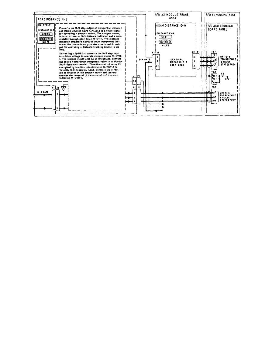 Figure 4-5.-Precise-access blocked text.
In each basic shape is inscribed the circuit-identifier
line. Monitors are indicated in a solid black background
code that identifies the actual component. In addition,
box with white lettering.
the coded arrows superimposed on the signal-flow lines
Front panel indicators and other recognizable
that tie these shapes together are again used to identify
indications with front panel markings, as applicable, and
the signals being processed. Also superimposed over
their associated cabinet nomenclature are located along
these block diagrams are shades of gray that indicate the
the top of the chart, If an event fails to happen, fault
level of containment of the components or other circuit
isolation is simplified by the indexing on the operator's
elements in the equipment through which the signal or
chart. This indexing will lead the troubleshooter to the
signals pass. Again there is blocked text on the facing
proper maintenance dependency chart and the circuit
page (fig. 4-5).
chain upon which the missing event depends. The
Detailed cabling information between all
troubleshooter merely associates the operational step
assemblies is shown on the precise-access blocked
and the event that did not occur to find the pertinent
diagram. In cases of large complex equipment, however,
circuit chain. A vertical column on the left side of the
power circuit cabling is detailed on power distribution
page contains the turn-on procedure in a sequence of
diagrams.
steps consistent with the engineering designed plan of
turn-on. Also in the left-hand column, boxed and
indented, are checkout procedural steps that can be
OPERATING PROCEDURES
performed at any time during operation. These checkout
steps will give an indication of the functional
Procedures that explain how to operate equipment
performance and will provide a sound basis for selection
under normal and emergency conditions are included in
of operator, preventive-maintenance checks.
the operating procedures. Manuals for some equipment
contain an operating chart that establishes a turn-on and
MAINTENANCE DEPENDENCY CHART
checkout procedure. The chart displays chronologically
all indications that can be recognized from outside the
equipment. The indications are events, such as meter
One of the most important features of the SIMM is
readings, lights, synchro rotating, or motor running
its troubleshooting tool, the maintenance dependency
noise, that can be recognized by the human senses.
chart (MDC). In addition to front panel marked
Shaded bands stretching across the chart show the time
indicators displayed across the top of the page, it
lapse between events. All simultaneous events for a
contains the various assemblies or circuit elements
given step of the procedure appear on one horizontal
through which a signal passes, as well as their chassis
4-5
|
|
Privacy Statement - Press Release - Copyright Information. - Contact Us |
