 |
|||
|
Page Title:
Figure 3-11.-Main motor controller: (A) Wiring diagram; (B) Schematic. |
|
||
| ||||||||||
|
|
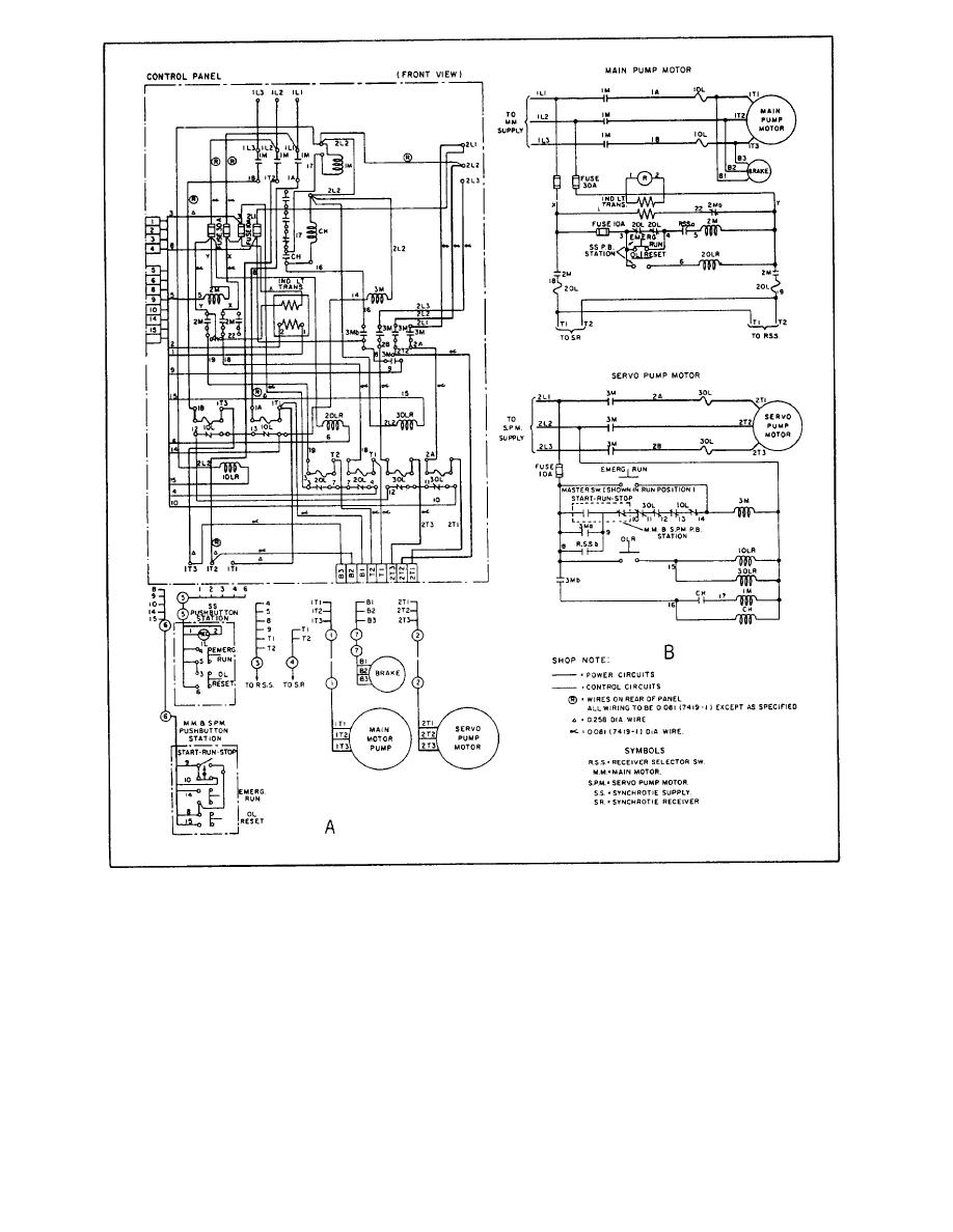 Figure 3-11.-Main motor controller: (A) Wiring diagram; (B) Schematic.
understanding how the circuit operates are omitted for
simplicity. Figure 3-11, view B, shows the schematic
diagram for the steering system main motor controller.
The electrical schematic diagram is used to describe
the electrical operation of a particular equipment,
circuit, or system. It is not drawn to scale and usually
Electronic prints are similar to electrical prints.
does not show the relative positions of the various
However, they are usually more difficult to read than
components. Parts and connections not essential to
3-17
|
|
Privacy Statement - Press Release - Copyright Information. - Contact Us |
